Board:lenovo/x201: Difference between revisions
No edit summary |
|||
| (26 intermediate revisions by 2 users not shown) | |||
| Line 2: | Line 2: | ||
Thanks for your interest in Lenovo X201 port. | Thanks for your interest in Lenovo X201 port. | ||
Issues: | Issues: | ||
* Sometimes Gnome starts to think that battery is 10 time larger than real. Information from sysfs remains correct. Doesn't appear in newer gnome | |||
* Yellow USB port is not powered when computer is shut down or in S3. | |||
* Sometimes Gnome starts to think that battery is 10 time larger than real | |||
Information from sysfs remains correct. | |||
Tested: | Tested: | ||
* RAM module combinations of 4G+4G, 4G, 2G+2G,4G+2G, 2G | * RAM module combinations of 4G+4G, 4G, 2G+2G,4G+2G, 2G | ||
* suspend to RAM (S3) | |||
* USB | * USB | ||
* Video (both internal and VGA) | * Video (both internal and VGA) | ||
* Expresscard slot | * Expresscard slot (including hotplug) | ||
* Sound | * Sound | ||
* LAN | * LAN | ||
* mini-PCIe slots (both wlan and wwan) | * mini-PCIe slots (both wlan and wwan) | ||
* Linux (through GRUB-as-payload) | * Linux (through GRUB-as-payload) | ||
* Windows (through GRUB-as-payload loading SeaBIOS image from disk) | * Windows (through GRUB-as-payload loading SeaBIOS image from disk; you have to use extracted VGA blob, dumped from memory isn't good enough) | ||
* SD card slot | * SD card slot | ||
* Thermal management | * Thermal management | ||
* Fingerprint reeader. | |||
* Webcam | |||
* Bluetooth | |||
* Digitizer on X201t variant. | |||
Not tested: | Not tested: | ||
* Modem | * Modem | ||
== proprietary components status == | == proprietary components status == | ||
* CPU Microcode | * CPU Microcode | ||
* VGA option rom (optional): you need it if you wantgraphics in SeaBIOS but most payloads should work without it (text mode) | * VGA option rom (optional): you need it if you wantgraphics in SeaBIOS but most payloads should work without it (text mode or corebootfb mode) | ||
* ME(Management Engine) => you do not have to touch it(just leave it where it is) | * ME(Management Engine) => you do not have to touch it(just leave it where it is) | ||
* EC(Embedded Controller) => you do not have to touch it(just leave it where it is) | * EC(Embedded Controller) => you do not have to touch it(just leave it where it is) | ||
== Code == | == Code == | ||
* [http://review.coreboot.org/#/c/ | * [http://review.coreboot.org/#/c/4514/ The code has been merged into coreboot master] | ||
$ git clone http://review.coreboot.org/p/coreboot | |||
== Flashing == | == Flashing == | ||
Flash in X201 is divided roughly in 4 parts: | Flash in X201 is divided roughly in 4 parts: | ||
| Line 53: | Line 57: | ||
* Remove the keyboard. | * Remove the keyboard. | ||
* Connect your external SPI flasher to the SPI chip which is under keyboard, | * Connect your external SPI flasher to the SPI chip which is under keyboard, | ||
around the position of trackpoint under protective layer. I recommend using | around the position of trackpoint under protective layer. | ||
SOIC clip. Depending on the flasher you use, you may have to use separate | {| | ||
|[[File:Lenovo-x201-bios-location-arrow.png |200px|thumb|center|found it!]] | |||
|[[File:X201_flash_location.png |200px|thumb|center|under the keyboard]] | |||
|} | |||
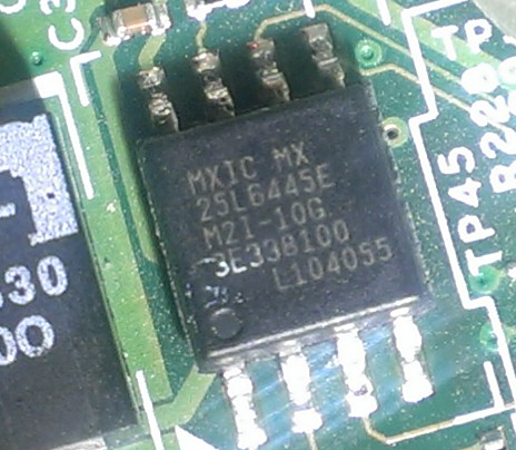
[[File:Spi-soic8-25L6445E.png|200px|thumb|right|The flash chip]] | |||
I recommend using SOIC-8 clip. Depending on the flasher you use, you may have to use separate | |||
3.3V source. Make sure not to feed more than 3.3V ot the chip. I used | 3.3V source. Make sure not to feed more than 3.3V ot the chip. I used | ||
buspirate as flasher and 3.3V power lines from another computer. | buspirate as flasher and 3.3V power lines from another computer. | ||
| Line 64: | Line 74: | ||
CS (white) MISO (black) N/C ground (brown) | CS (white) MISO (black) N/C ground (brown) | ||
=== back (touchpad) === | === back (touchpad) === | ||
* Read the flash. Twice. Compare the files to be sure. Save a copy of it on | * Read the flash. Twice. Compare the files to be sure. Save a copy of it on | ||
external media. | external media. | ||
flashrom -p <yourprogrammer> -r flash.bin | |||
flashrom -p <yourprogrammer> -r flash2.bin | |||
diff flash.bin flash2.bin | |||
If you have trouble reading the chip successfully, | |||
the most common problems are | |||
*insufficient power supply | |||
*bad contacts | |||
*too long wires | |||
*bad pinout | |||
The cable shipped with buspirate was too long, and needed to be trimmed. | |||
See also [http://flashrom.org/ISP In-System Programming] | |||
* Recover descriptor and me firmare: | * Recover descriptor and me firmare: | ||
dd if=flash.bin of=coreboot/3rdparty/mainboard/lenovo/x201/descriptor.bin \ | dd if=flash.bin of=coreboot/3rdparty/mainboard/lenovo/x201/descriptor.bin \ | ||
count=12288 bs=1M iflag=count_bytes | count=12288 bs=1M iflag=count_bytes | ||
dd if=flash.bin of=coreboot/3rdparty/mainboard/lenovo/x201/me.bin \ | dd if=flash.bin of=coreboot/3rdparty/mainboard/lenovo/x201/me.bin \ | ||
skip=12288 count=5230592 bs=1M iflag=count_bytes | skip=12288 count=5230592 bs=1M iflag=count_bytes,skip_bytes | ||
* Compile coreboot | * Compile coreboot | ||
* Flash the resulting build/coreboot.rom | * Flash the resulting build/coreboot.rom | ||
| Line 87: | Line 113: | ||
===identify the regions=== | |||
[root@ | [root@x201 ~]# flashrom -r bios.bin -pinternal:laptop=force_I_want_a_brick | ||
flashrom v0.9.6.1- | flashrom v0.9.6.1-r1563 on Linux 3.10-1-grml-amd64 (x86_64) | ||
flashrom is free software, get the source code at http://www.flashrom.org | flashrom is free software, get the source code at http://www.flashrom.org | ||
Calibrating delay loop... OK. | Calibrating delay loop... OK. | ||
Found chipset "Intel QM57". Enabling flash write... WARNING: SPI Configuration Lockdown activated. | |||
FREG0: WARNING: Flash Descriptor region (0x00000000-0x00000fff) is read-only. | |||
FREG2: WARNING: Management Engine region (0x00003000-0x004fffff) is locked. | |||
PR0: WARNING: 0x007d0000-0x01ffffff is read-only. | |||
Found chipset "Intel | |||
FREG2: WARNING: Management Engine region (0x00003000- | |||
Please send a verbose log to flashrom@flashrom.org if this board is not listed on | Please send a verbose log to flashrom@flashrom.org if this board is not listed on | ||
http://flashrom.org/Supported_hardware#Supported_mainboards yet. | http://flashrom.org/Supported_hardware#Supported_mainboards yet. | ||
| Line 125: | Line 129: | ||
If you force flashrom you will get no support if something breaks. | If you force flashrom you will get no support if something breaks. | ||
OK. | OK. | ||
Found | Found Macronix flash chip "MX25L6405" (8192 kB, SPI) at physical address 0xff800000. | ||
Reading flash... | Reading flash... FAILED. | ||
it will print the ME regions: | it will print the ME regions: | ||
FREG2: WARNING: Management Engine region (0x00003000- | FREG2: WARNING: Management Engine region (0x00003000-0x004fffff) is locked. | ||
it will also print the chip: | it will also print the chip: | ||
Found | Found Macronix flash chip "MX25L6405" (8192 kB, SPI) at physical address 0xff800000. | ||
=> verify | '''But as in this case, flashrom might misidentify the chip''', this output is from [[Media:Spi-soic8-25L6445E.png|this MX25L6445E]] | ||
visually verify your chip's part number and find an [http://www.macronix.com/QuickPlace/hq/PageLibrary4825740B00298A3B.nsf/h_Index/3F21BAC2E121E17848257639003A3146/$File/MX25L6445E,%203V,%2064Mb,%20v1.8.pdf appropriate datasheet ] | |||
=>verify that its voltage matches with the programmer voltage... | |||
* Then man flashrom says: | * Then man flashrom says: | ||
-l, --layout <file> | -l, --layout <file> | ||
Read ROM layout from <file>. | |||
flashrom supports ROM layouts. This allows you to flash | |||
certain parts of the flash chip only. A ROM layout file contains multiple lines | |||
with the following syntax: | |||
startaddr:endaddr imagename | |||
startaddr and endaddr are hexadecimal addresses within the ROM | |||
file and do not refer to any physical address. Please note that using a 0x | |||
prefix for those hexadecimal numbers is not necessary, but you can't | |||
specify decimal/octal numbers. imagename is an arbitrary name for the | |||
region/image from startaddr to endaddr (both addresses included). | |||
Example: | |||
00000000:00008fff gfxrom | 00000000:00008fff gfxrom | ||
| Line 153: | Line 163: | ||
00040000:0007ffff fallback | 00040000:0007ffff fallback | ||
If you only want to update the image named normal in a ROM based on the layout above, run | |||
flashrom -p prog --layout rom.layout --image normal -w some.rom | |||
To update only the images named normal and fallback, run: | |||
flashrom -p prog -l rom.layout -i normal -i fallback -w some.rom | |||
Overlapping sections are not supported. | |||
Revision as of 23:02, 14 August 2014
Status
Thanks for your interest in Lenovo X201 port. Issues:
- Sometimes Gnome starts to think that battery is 10 time larger than real. Information from sysfs remains correct. Doesn't appear in newer gnome
- Yellow USB port is not powered when computer is shut down or in S3.
Tested:
- RAM module combinations of 4G+4G, 4G, 2G+2G,4G+2G, 2G
- suspend to RAM (S3)
- USB
- Video (both internal and VGA)
- Expresscard slot (including hotplug)
- Sound
- LAN
- mini-PCIe slots (both wlan and wwan)
- Linux (through GRUB-as-payload)
- Windows (through GRUB-as-payload loading SeaBIOS image from disk; you have to use extracted VGA blob, dumped from memory isn't good enough)
- SD card slot
- Thermal management
- Fingerprint reeader.
- Webcam
- Bluetooth
- Digitizer on X201t variant.
Not tested:
- Modem
proprietary components status
- CPU Microcode
- VGA option rom (optional): you need it if you wantgraphics in SeaBIOS but most payloads should work without it (text mode or corebootfb mode)
- ME(Management Engine) => you do not have to touch it(just leave it where it is)
- EC(Embedded Controller) => you do not have to touch it(just leave it where it is)
Code
$ git clone http://review.coreboot.org/p/coreboot
Flashing
Flash in X201 is divided roughly in 4 parts:
- Descriptor (12K)
- ME firmware (5M-12K)
- Rewriteable flash (3M-96K)
- Locked bootblock (96K)
Descriptor and bootblock are read-only. ME firmware is not readable. Rewriteable region can be rewritten easily with flashrom.
For coreboot we need to preserve descriptor and ME firmware while overwriting rewriteable region and bootblock. To achieve this there are 2 ways:
- External flasher.
- Unlock bootblock
For the first one proceeds as follows:
- Turn off your laptop, remove battery and AC adapter.
- Remove the keyboard.
- Connect your external SPI flasher to the SPI chip which is under keyboard,
around the position of trackpoint under protective layer.
 |

I recommend using SOIC-8 clip. Depending on the flasher you use, you may have to use separate 3.3V source. Make sure not to feed more than 3.3V ot the chip. I used buspirate as flasher and 3.3V power lines from another computer. The pinout is as follows, the colors are buspirate colors
 ===  front (display) ====
 3.3V (red)   N/C          violet (CLK)  MOSI (gray)
      |        |             |              |
 dot  |        |             |              |
 CS (white)   MISO (black) N/C           ground (brown)
 ===  back (touchpad) ===
- Read the flash. Twice. Compare the files to be sure. Save a copy of it on
external media.
flashrom -p <yourprogrammer> -r flash.bin
flashrom -p <yourprogrammer> -r flash2.bin
diff flash.bin flash2.bin
If you have trouble reading the chip successfully, the most common problems are
- insufficient power supply
- bad contacts
- too long wires
- bad pinout
The cable shipped with buspirate was too long, and needed to be trimmed.
See also In-System Programming
- Recover descriptor and me firmare:
 dd if=flash.bin of=coreboot/3rdparty/mainboard/lenovo/x201/descriptor.bin \
   count=12288 bs=1M iflag=count_bytes
 dd if=flash.bin of=coreboot/3rdparty/mainboard/lenovo/x201/me.bin \
   skip=12288 count=5230592 bs=1M iflag=count_bytes,skip_bytes
- Compile coreboot
- Flash the resulting build/coreboot.rom
The other way has never been successfully used but it's known that the locking mechanism is in bootblock itself and that original firmware has a way to update it as follows:
- Flash an update of rewriteable region. On next boot bootblock parses the
image and sees that it contains a compressed copy of new bootblock. That copy is uncompressed and flashed. A way to unlock the bootblock would be to modify a firmware update to have a copy of bootblock without protection. For this you need to compress the modified block to fit into original space. The compression used is Lempel-Ziv- Huffman variant. I've written a compressor for it but unfortunately it's not performant enough.
identify the regions
[root@x201 ~]# flashrom -r bios.bin -pinternal:laptop=force_I_want_a_brick
flashrom v0.9.6.1-r1563 on Linux 3.10-1-grml-amd64 (x86_64)
flashrom is free software, get the source code at http://www.flashrom.org

Calibrating delay loop... OK.
Found chipset "Intel QM57". Enabling flash write... WARNING: SPI Configuration Lockdown activated.
FREG0: WARNING: Flash Descriptor region (0x00000000-0x00000fff) is read-only.
FREG2: WARNING: Management Engine region (0x00003000-0x004fffff) is locked.
PR0: WARNING: 0x007d0000-0x01ffffff is read-only.
Please send a verbose log to flashrom@flashrom.org if this board is not listed on
http://flashrom.org/Supported_hardware#Supported_mainboards yet.
Writes have been disabled. You can enforce write support with the
ich_spi_force programmer option, but it will most likely harm your hardware!
If you force flashrom you will get no support if something breaks.
OK.
Found Macronix flash chip "MX25L6405" (8192 kB, SPI) at physical address 0xff800000.
Reading flash... FAILED.
it will print the ME regions:
FREG2: WARNING: Management Engine region (0x00003000-0x004fffff) is locked.
it will also print the chip:
Found Macronix flash chip "MX25L6405" (8192 kB, SPI) at physical address 0xff800000.
But as in this case, flashrom might misidentify the chip, this output is from this MX25L6445E
visually verify your chip's part number and find an appropriate datasheet
=>verify that its voltage matches with the programmer voltage...
- Then man flashrom says:
       -l, --layout <file>
               Read ROM layout from <file>.

               flashrom  supports  ROM  layouts. This allows you to flash
               certain parts of the flash chip only. A ROM layout file contains multiple lines
               with the following syntax:

                 startaddr:endaddr imagename

               startaddr and endaddr are hexadecimal addresses within the ROM
               file and do not refer to any physical address. Please note that using a 0x
               prefix  for  those hexadecimal  numbers  is  not necessary, but you can't
               specify decimal/octal numbers.  imagename is an arbitrary name for the
               region/image from  startaddr to endaddr (both addresses included).

               Example:

                00000000:00008fff gfxrom
                00009000:0003ffff normal
                00040000:0007ffff fallback

               If you only want to update the image named normal in a ROM based on the layout above, run

                  flashrom -p prog --layout rom.layout --image normal -w some.rom

                To update only the images named normal and fallback, run:

                  flashrom -p prog -l rom.layout -i normal -i fallback -w some.rom

               Overlapping sections are not supported.