Developer Manual/Tools: Difference between revisions
No edit summary |
|||
| (20 intermediate revisions by one other user not shown) | |||
| Line 9: | Line 9: | ||
** Windows as a development platform tends to work, but is more complicated to set up, less commonly used (at least outside corporate firewalls) and tends to be slower in operation. Setup instructions: [[Developer Manual/Tools/Cygwin]], [[Developer Manual/Tools/MinGW]] | ** Windows as a development platform tends to work, but is more complicated to set up, less commonly used (at least outside corporate firewalls) and tends to be slower in operation. Setup instructions: [[Developer Manual/Tools/Cygwin]], [[Developer Manual/Tools/MinGW]] | ||
When developing, you will, at some point, have flashed code that cannot boot your mainboard. | |||
To overcome that, you will need: | |||
* A way to reflash when that happens. | |||
* A way to get some output to get debug logs, to understand what's happening. | |||
=== | This page list many tools that can help in debugging, relfashing, or both. | ||
=== Flash chip related === | |||
====WARNING: flash chip swapping==== | |||
<div style="color: red">If you're going to work on this board, you need a backup plan in the event you flash a faulty BIOS image. | <div style="color: red">If you're going to work on this board, you need a backup plan in the event you flash a faulty BIOS image. | ||
The secondary chip must have different size (preferable greater capacity) than the primary chip (factory chip) that comes with the board in order to avoid accidents: flashrom will not burn the Coreboot image (<code>sudo flashrom -p internal -w new.bin [...] Error: Image size doesn't match</code>) if the size of the hardware chip mismatch the Coreboot image configured ''ROM chip size''. This is a good thing as it will save you from accidentally burning Cooreboot to the primary chip if you forget to toggle the hardware switch to the secondary chip. Chips with equal size will likely make you break the board one day. You have been warned!</div> | The secondary chip must have different size (preferable greater capacity) than the primary chip (factory chip) that comes with the board in order to avoid accidents: flashrom will not burn the Coreboot image (<code>sudo flashrom -p internal -w new.bin [...] Error: Image size doesn't match</code>) if the size of the hardware chip mismatch the Coreboot image configured ''ROM chip size''. This is a good thing as it will save you from accidentally burning Cooreboot to the primary chip if you forget to toggle the hardware switch to the secondary chip. Chips with equal size will likely make you break the board one day. You have been warned!</div> | ||
==== External Flash programmer to flash your mainboard flash chip ==== | |||
==== External | |||
External programmers are not always necessary. Use your mainboard as a programmer instead. Boot up with a known-good image, then unplug the (DIP32, PLCC32, or DIP8) ROM chip while powered on. Reflash that secondary piece and try a reboot. Many boards allow for more than one type | External programmers are not always necessary. Use your mainboard as a programmer instead. Boot up with a known-good image, then unplug the (DIP32, PLCC32, or DIP8) ROM chip while powered on. Reflash that secondary piece and try a reboot. Many boards allow for more than one type | ||
| Line 30: | Line 31: | ||
* [http://dangerousprototypes.com/docs/Bus_Pirate Bus Pirate v3/v4]: SPI programmer, similar to but less expensive than the Dediprog SF100. Really slow. If you're using it, try at least http://flashrom.org/Bus_Pirate#Speedup to get a somewhat acceptable speed out of it. | * [http://dangerousprototypes.com/docs/Bus_Pirate Bus Pirate v3/v4]: SPI programmer, similar to but less expensive than the Dediprog SF100. Really slow. If you're using it, try at least http://flashrom.org/Bus_Pirate#Speedup to get a somewhat acceptable speed out of it. | ||
* [http://www.flashrom.org/RaspberryPi Raspberry Pi] (or any other development board with a fast SPI bus): SPI programmer, rougly as fast as the Dediprog SF100, but as cheap as the Bus Pirate. | * [http://www.flashrom.org/RaspberryPi Raspberry Pi] (or any other development board with a fast SPI bus): SPI programmer, rougly as fast as the Dediprog SF100, but as cheap as the Bus Pirate. | ||
* [https://developer.mbed.org/users/hudakz/code/STM32F103C8T6_Hello/ Blue Pill] | |||
Some programmers aren't and works with other software: | Some programmers aren't and works with other software: | ||
* [http://www.loet.de/flasher_en.html IDE adapter for PLCC32 & DIP32 sockets]: Has Linux 2.4 & 2.6 drivers $/ | * [http://www.loet.de/flasher_en.html IDE adapter for PLCC32 & DIP32 sockets]: Has Linux 2.4 & 2.6 drivers $/� ~48 (kit �33) free manual with schematics & component list downloadable (component cost approx. �5) | ||
* [http://www.conitec.net/english/software.htm GALEP-4]: Has [http://www.conitec.net/hardware/down/galep-linux-alpha1.html beta Linux drivers] ~$300. See [[Galep IV]] for a description on how to get the more modern Windows software working in Linux with '''wine'''. | * [http://www.conitec.net/english/software.htm GALEP-4]: Has [http://www.conitec.net/hardware/down/galep-linux-alpha1.html beta Linux drivers] ~$300. See [[Galep IV]] for a description on how to get the more modern Windows software working in Linux with '''wine'''. | ||
* [http://www.mcumall.com/ Willem Universal EPROM Programmer]: DOS, Windows software, work has started on Linux drivers, quite many types of EEPROM asf. ~ | * [http://www.mcumall.com/ Willem Universal EPROM Programmer]: DOS, Windows software, work has started on Linux drivers, quite many types of EEPROM asf. ~ �35 | ||
* https://web.archive.org/web/20120305211839/http://www.xeltek.com/pages.php?pageid=8 | * https://web.archive.org/web/20120305211839/http://www.xeltek.com/pages.php?pageid=8 | ||
==== BIOS Savior ==== | ==== Chip swapping tools and techniques ==== | ||
===== PC Engines lpc1A ===== | |||
[http://pcengines.ch/lpc1a.htm The LPC1A] is most useful if you are working on machines from the ALIX family. | |||
It is a PCB with a second flash and socket that plugs into the LPC header of the ALIX boards. | |||
It could also be useful if you can expose an LPC header on another board. | |||
Schematics are freely downloadable. | |||
===== BIOS Savior ===== | |||
[[Image:Bios savior.jpg|thumb|right|An installed BIOS Savior.]] | [[Image:Bios savior.jpg|thumb|right|An installed BIOS Savior.]] | ||
| Line 48: | Line 61: | ||
* http://www.ioss.com.tw/web/English/RD1BIOSSavior.html | * http://www.ioss.com.tw/web/English/RD1BIOSSavior.html | ||
==== Top Hat Flash ==== | ===== Top Hat Flash ===== | ||
A similar function is achieved by the '''Top Hat Flash''' which comes at no extra cost with many Elitegroup, and some GIGABYTE and Albatron mainboards like ECS KN3 SLI2 Extreme. | A similar function is achieved by the '''Top Hat Flash''' which comes at no extra cost with many Elitegroup, and some GIGABYTE and Albatron mainboards like ECS KN3 SLI2 Extreme. | ||
| Line 60: | Line 73: | ||
<br clear="all" /> | <br clear="all" /> | ||
==== Dual flash ==== | ===== Dual flash ===== | ||
[[File:Dual_parallel_flash.jpg|200px|thumb|right|Dual flash "pie". One for keeping working firmware image. Flash chips are selectable by a tumbler switch]] | [[File:Dual_parallel_flash.jpg|200px|thumb|right|Dual flash "pie". One for keeping working firmware image. Flash chips are selectable by a tumbler switch]] | ||
| Line 86: | Line 99: | ||
</gallery> | </gallery> | ||
=== | === Flash emulators (used to flash and debug) === | ||
==== Artecgroup programmable LPC dongle ==== | |||
=== Artecgroup programmable LPC dongle === | |||
The [[Artecgroup programmable LPC dongle]] (Now called FlexyICE) is a ROM emulator and debugging tool. | The [[Artecgroup programmable LPC dongle]] (Now called FlexyICE) is a ROM emulator and debugging tool. | ||
See [http://www.artecgroup.com/products/hardware-products/programmable-lpc-dongle.html] and [http://www.opencores.org/projects.cgi/web/usb_dongle_fpga/overview]. | See [http://www.artecgroup.com/products/hardware-products/programmable-lpc-dongle.html] and [http://www.opencores.org/projects.cgi/web/usb_dongle_fpga/overview]. | ||
= | ==== In Circuit Emulator hardware debugger ==== | ||
=== In Circuit Emulator hardware debugger === | |||
Allows very time-saving burn/debug cycles with added tracing capabilities but somewhat costly. | Allows very time-saving burn/debug cycles with added tracing capabilities but somewhat costly. | ||
=== EPROM emulators === | ==== EPROM emulators ==== | ||
These hardware devices pretend to be an EEPROM chip. | These hardware devices pretend to be an EEPROM chip. | ||
| Line 116: | Line 120: | ||
=== Getting some output === | === Getting some output === | ||
[[Console and outputs]] lists the various ways of getting the boot logs, with the advantages, requirements, and limitations of each way. | |||
==== USB debug devices ==== | ==== USB debug devices ==== | ||
| Line 132: | Line 138: | ||
A [[POST card]] will save your life: it's the only output device (beside beeper) you have during the boot process. | A [[POST card]] will save your life: it's the only output device (beside beeper) you have during the boot process. | ||
==== Oscilloscope ==== | |||
Unlike consoles or debug ports outputs, oscilloscopes are used to view electronic signals. | |||
This can save you a lot of time when dealing with low level hardware busses. | |||
Consider '''logic analyzers''' as alternative. | |||
=== Other === | === Other === | ||
Latest revision as of 17:10, 22 August 2017
Before starting to work on coreboot support for a new mainboard and/or chipset you'll want a few development tools (both hardware and software). Not all of them are strictly required, a lot depends on your specific task and needs.
Basic requirements
- A mainboard you want to port coreboot to, preferably with long manufacturing lifespan.
- Datasheets
- A development machine (ideally separate from your target system, though there are some mavericks who use the target for development)
- A Linux/UNIX machine is recommended
- Windows as a development platform tends to work, but is more complicated to set up, less commonly used (at least outside corporate firewalls) and tends to be slower in operation. Setup instructions: Developer Manual/Tools/Cygwin, Developer Manual/Tools/MinGW
When developing, you will, at some point, have flashed code that cannot boot your mainboard. To overcome that, you will need:
- A way to reflash when that happens.
- A way to get some output to get debug logs, to understand what's happening.
This page list many tools that can help in debugging, relfashing, or both.
WARNING: flash chip swapping
sudo flashrom -p internal -w new.bin [...] Error: Image size doesn't match) if the size of the hardware chip mismatch the Coreboot image configured ROM chip size. This is a good thing as it will save you from accidentally burning Cooreboot to the primary chip if you forget to toggle the hardware switch to the secondary chip. Chips with equal size will likely make you break the board one day. You have been warned!External Flash programmer to flash your mainboard flash chip
External programmers are not always necessary. Use your mainboard as a programmer instead. Boot up with a known-good image, then unplug the (DIP32, PLCC32, or DIP8) ROM chip while powered on. Reflash that secondary piece and try a reboot. Many boards allow for more than one type of flash to be programmed, but clearly are less versatile than real programmers.
Many programmers are supported by flashrom:
- RTL8139 NIC (PCI network card) with 32 pin socket and the appropriate ZIF socket adapter with flashrom. this is a low cost approach. Check, whether flashrom will recognize your flash part in this scenario.
- Dediprog SF100:High speed spi programmer, can be used under both windows and linux(with flashrom). See SF100 Usage for detail description.
- Bus Pirate v3/v4: SPI programmer, similar to but less expensive than the Dediprog SF100. Really slow. If you're using it, try at least http://flashrom.org/Bus_Pirate#Speedup to get a somewhat acceptable speed out of it.
- Raspberry Pi (or any other development board with a fast SPI bus): SPI programmer, rougly as fast as the Dediprog SF100, but as cheap as the Bus Pirate.
- Blue Pill
Some programmers aren't and works with other software:
- IDE adapter for PLCC32 & DIP32 sockets: Has Linux 2.4 & 2.6 drivers $/� ~48 (kit �33) free manual with schematics & component list downloadable (component cost approx. �5)
- GALEP-4: Has beta Linux drivers ~$300. See Galep IV for a description on how to get the more modern Windows software working in Linux with wine.
- Willem Universal EPROM Programmer: DOS, Windows software, work has started on Linux drivers, quite many types of EEPROM asf. ~ �35
- https://web.archive.org/web/20120305211839/http://www.xeltek.com/pages.php?pageid=8
Chip swapping tools and techniques
PC Engines lpc1A
The LPC1A is most useful if you are working on machines from the ALIX family.
It is a PCB with a second flash and socket that plugs into the LPC header of the ALIX boards.
It could also be useful if you can expose an LPC header on another board.
Schematics are freely downloadable.
BIOS Savior

The BIOS Savior is a tool that plugs into and replaces the original mainboard Flash device. The BIOS Savior has its own Flash device and a socket for the original mainboard Flash device (PLCC or DIP versions are available). It features a switch to allow the developer to choose between which Flash device is accessed by the mainboard during read and write cycles.
This device helps to minimize the amount of hot swapping required and reduces mechanical and electrical stress on the BIOS chips.
The BIOS Savior is available from:
Top Hat Flash
A similar function is achieved by the Top Hat Flash which comes at no extra cost with many Elitegroup, and some GIGABYTE and Albatron mainboards like ECS KN3 SLI2 Extreme.
As you can guess from the photo to the side, it is two plcc sockets soldered together. The upper one carries a spare BIOS chip as a fallback / failsafe secondary bootable BIOS. By means of some 'obscure' cicuitry, the additional, secondary chip is being booted from, if you manually press / stick the TOP HAT FLASH onto your primary BIOS chip on the mainboard. Sadly, this simple technique does not seem to work with other boards right away.
After bootup, it can manually be lifted off the original BIOS chip, so the original BIOS can be reflashed after a failure. The RST# pin is wired to OE# on the spare chip, otherwise it's wired 1:1. Top Hat Flash is equipped with a Winbond W39V040AP FWH. It may rely on particular circuitry on the mainboard to operate.

Dual flash

You may DIY yours dual flash device. As an example look here: Developer Manual/Tools/Dual Flash
Chip removal tools
If you're hot-swapping your BIOS chips (i.e., removing the chip while your computer is running, then inserting another one) you'll usually need some tools.
There are different tools for DIP and PLCC chips (see photos). You can find them in most electronics stores, usually. Both types cost roughly 5-10 Euros.
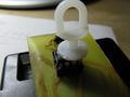
Another very nifty idea is clipping off the needle point of normal office push pins, and then attaching them to (PLCC) ROM chips with super glue. That makes it pretty easy to insert and remove the ROM chips without extra tools.
Since after bootup, flash mem is not accessed anymore, you can even hot plug (plug in and out while PC powered on) push pin flashes. This way you save an external EEPROM programmer and mimic the procedure of top hat flash. Make sure you do not short circuit anything, though.
-
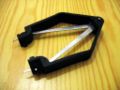
PLCC32 BIOS removal tool.
-
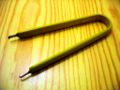
DIP32 BIOS removal tool.
-
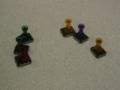
Push pins with cut off needles, attached to ROM chips with super glue.
-
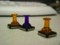
More push pins on ROM chips.
-
Alternative: with something used to support curtains.


Flash emulators (used to flash and debug)
Artecgroup programmable LPC dongle
The Artecgroup programmable LPC dongle (Now called FlexyICE) is a ROM emulator and debugging tool. See [1] and [2].
In Circuit Emulator hardware debugger
Allows very time-saving burn/debug cycles with added tracing capabilities but somewhat costly.
EPROM emulators
These hardware devices pretend to be an EEPROM chip.
- http://www.tech-tools.com/romtools.htm
- http://xtronics.com/memory/pktROM.htm
- http://www.tribalmicro.com/multirom/
- http://www.linuxselfhelp.com/HOWTO/Diskless-HOWTO-10.html (a larger list -- outdated)
Getting some output
Console and outputs lists the various ways of getting the boot logs, with the advantages, requirements, and limitations of each way.
USB debug devices

An alternative to a serial console may be a USB debug device. They are not so common, yet. Their advantage is higher speed than a serial console. One might hook an FPGA to it for profiling purposes or some automated checks. Accessing a USB debug device from within BIOS is not different than other USB devices, and is part of the USB standard.
See also EHCI Debug Port and DIY_EHCI_debug_dongle.
Serial console
While being less common on laptops, the serial console is very well supported by software. Accessing it often requires a Null modem cable and one of the many programs written for that purpose.
POST card
A POST card will save your life: it's the only output device (beside beeper) you have during the boot process.
Oscilloscope
Unlike consoles or debug ports outputs, oscilloscopes are used to view electronic signals. This can save you a lot of time when dealing with low level hardware busses. Consider logic analyzers as alternative.
Other
Compact Flash IDE adaptor
Solid state disks (e.g. CompactFlash cards) save time during the repeated boot process compared with regular hard disks.
- http://siliconkit.dnsalias.com/cart/index.tcfdp.html
- http://www.cwlinux.com/eng/products/products_ide2cf.php
- http://www.mini-box.com/s.nl/sc.8/category.14/.f
- http://www.acscontrol.com/Index_ACS.asp?Page=/Pages/Products/CompactFlash/IDE_To_CF_Adapter.htm
- http://www.pcengines.ch/cflash.htm
- http://www.psism.com/adcf.htm
- http://www.hsc-us.com/industrial/adapter/ATP.html (2xCF, one with hotswap!)
- http://www.mesanet.com/ (Choose DISK EMULATORS then CFADPTHD in the menu. 2xCF)