FAQ
The wiki is being retired!
Documentation is now handled by the same processes we use for code: Add something to the Documentation/ directory in the coreboot repo, and it will be rendered to https://doc.coreboot.org/. Contributions welcome!
General
What is coreboot?
coreboot (formerly known as LinuxBIOS) is a Free Software project aimed at replacing the proprietary BIOS (firmware) you can find in most of today's computers.
It performs just a little bit of hardware initialization and then executes a so-called payload.
Some of the many possible payloads are: a Linux kernel, FILO, GRUB2, OpenBIOS, Open Firmware, SmartFirmware, GNUFI (UEFI), Etherboot, ADLO (for booting Windows 2000 and OpenBSD), Plan 9, or memtest86.
The initial motivation for the project was maintenance of large clusters, but unsurprisingly, interest and contributions have come from people with varying backgrounds. The latest version of coreboot can be used in a wide variety of scenarios including clusters, embedded systems, desktop PCs, servers, and more.
For more information, see History.
Why do we need coreboot?
Why do we need coreboot for cluster maintainance?
Current PCs used as cluster nodes depend on a vendor-supplied BIOS for booting. The BIOS in turn relies on inherently unreliable devices such as floppy disks and hard drives to boot the operating system. In addition, current BIOS software is unable to accommodate non-standard hardware making it difficult to support experimental work. The BIOS is slow and often erroneous and redundant and, most importantly, maintenance is a nightmare. Imagine walking around with a keyboard and monitor to every one of the 128 nodes in a cluster to change one BIOS setting.
coreboot with Linux as a payload (other payloads are possible!) gunzip's the Linux kernel straight out of NVRAM and essentially requires no moving parts other than the fan. It does a minimal amount of hardware initialization before jumping to the kernel start and lets Linux do the rest. As a result, it is much faster (current record 3 seconds), which has sparked interest in the consumer electronics community as well. Moreover, updates can be performed over the network.
Using a real operating system to boot another operating system provides much greater flexibility than using a simple netboot program or the BIOS. Because Linux is the boot mechanism, it can boot over standard Ethernet or over other interconnects such as Myrinet, Quadrics, or SCI. It can use SSH connections to load the kernel, or it can use the InterMezzo caching file system or traditional NFS. Cluster nodes can be as simple as they need to be perhaps as simple as a CPU and memory, no disk, no floppy, and no file system. The nodes will be much less autonomous thus making them easier to maintain.
Why do we need coreboot for other purposes?
Some aspects of DRM are not travelling well with the idea of a free computer system. As many computer magazines already pointed out, there may be future restrictions imposed by BIOSes, that a customer is little aware of before purchase and might not harmonize with the idea of freedom and/or security in some cases.
Who is working on coreboot?
The coreboot project was started in the winter of 1999 in the Advanced Computing Laboratory at Los Alamos National Laboratory (LANL) by Ron Minnich. Two undergraduate students, James Hendricks and Dale Webster spent their winter vacation putting together the proof of concept implementation.
Since then, a long list of people have contributed both in discussions and actual code. Please don't be shy and let us know if you are missing from the list. It's not a purposeful omission, just an unfortunate mistake.
Who is funding coreboot?
The LinuxBIOS project is funded by the Los Alamos Computer Science Institute and the Department of Energy's Office of Science.
See also the list of LinuxBIOS sponsors.
Users
Will coreboot work on my machine?
See the Supported Motherboards page for which mainboards are supported, and also the list of Supported Chipsets and Devices. See the Products page for a list of vendors selling products running coreboot.
If the above sources don't help, please send the following to the mailing list:
- Step 1: A very brief description of your system: CPU, northbridge, southbridge, mainboard and optionally other important details.
- Step 2: Linux lspci output for your system, generated by booting Linux via the original BIOS and runnning lspci.
- Step 3: Super I/O chip on the mainboard (report the model numbers on the actual chip, for example "Winbond W83627HF").
- Step 4: Type of BIOS device (see the question "How do I identify the BIOS chip on my mainboard?" below).
- Step 5: URL to the mainboard specifications page (optional).
- Step 6: Any other relevant information you can provide.
If you can't do step 1 above, please describe (as best you can) the specific CPU chip and the chipset used on the mainboard.
Usually in less than a day, someone will respond on the coreboot mailing list saying your mainboard is supported in the main coreboot source tree, it is currently in development, it is not yet supported or the manufacturer will not release information needed to provide coreboot support. In the latter case, please let the manufacturer know that you want coreboot support and his failure to release chipset information is making that very difficult.
What commercial products use coreboot?
See the products page.
Which different operating systems will coreboot boot?
coreboot should support almost any modern operating system which does not make BIOS calls:
- Linux (of course)
- Plan 9
- Windows 2000 (via ADLO)
coreboot does not support:
- We have tested some of the BSD OSes and have seen, that FreeBSD for example makes BIOS calls, which is not supported by coreboot. Possibly with help of the tool ADLO, it may be possible to boot FreeBSD like it is now, but the right thing to do, is to remove FreeBSD's dependence on BIOS calls.
- any DOS
- Windows versions older than Windows 2000 (they make BIOS calls) — (Does ADLO work with those versions?)
- MenuetOS (makes BIOS calls)
It appears feasible, however, to introduce some "legacy support" to coreboot in the future to support OSes like the abovementioned.
What chipsets and Super I/O devices are supported?
See the Supported Chipsets and Devices page.
Where is the mailing list archived?
See Mailinglist.
Is there a coreboot IRC channel?
Yes, see IRC.
Where do I get the code?
See the download page.
How do I build coreboot?
See the documentation.
How can I help with coreboot?
There are many ways how you can help us:
- Promote coreboot, tell all your friends about it, blog about it etc.
- Test coreboot, report any bugs you find, or let us know about any suggestions for improvements you have.
- Help us to make the list of Supported Motherboards and the list of Supported Chipsets and Devices bigger by contributing code. Please also read the Development Guidelines in that case.
- If you have a mainboard with USB2 (EHCI-controller) you can look if it supports the Debug Port and mail the information to us, if it is not already there.
- If you are familiar with microcontroller development, you might be able to build a debugging tool for the Debug Port. If you are successful, we like to hear about it.
- Test, if QNX or Solaris are able to boot on a mainboard with coreboot.
- Have a look at the list of open issues/bugs and try to reproduce them or (preferrably) fix them.
- Contact Ron Minnich or Stefan Reinauer for bigger projects related to coreboot.
- Contact us on the mailing list if you have any further questions or suggestions.
What do the abbreviations in this wiki stand for?
See Glossary.
Developers
Where can I buy BIOS chips (empty or pre-flashed)?
When developing or simply trying out coreboot you always need a means to revert to your old BIOS in case something goes wrong. One way to do this is to get an extra BIOS chip (PLCC or DIP) and copy your original BIOS image onto that chip (using Flashrom, for example). If you have a socketed BIOS (not soldered onto the mainboard), you can hot-swap the chips while your computer is running.
You have several options to get spare BIOS chips:
- Most local or online electronics dealers carry some, for example:
- Germany:
- http://www.bios-chip.de
- http://www.bios-fix.de
- http://www.bios-shop.com
- http://www.bios-chips.com
- http://www.conrad.de
- http://www.endrich.com/de/site.php/47385 (it's unknown whether they ship small quantities)
- UK:
- US:
- Germany:
- You can search eBay for BIOS chips (either empty ones or pre-flashed ones).
- You can rip out chips from old/broken mainboards and re-use them (you can check flea markets, eBay, etc. for cheap and/or broken mainboards).
What kind of hardware tools do I need?
A motherboard (or mainboard as coreboot calls it) that has a supported chipset on it. Ok... well not exactly. As long as you have the documentation for the chipset/mainboard and it's free of any NDA issues you can use an unsupported chipset/mainboard, but you have a twisty road ahead of you.
And of course you need a Linux development machine. The coreboot build environment is not supported on Windows. It may be possible to do it under cygwin but nobody has tried.
It's also handy to have one/some/all of the following:
PLAICE Programmer, Logic Analyzer and In-Circuit Emulator
PLAICE (In Development) see also /.slashdot The PLAICE is a powerful in circuit development tool that combines the features of programming and emulating FLASH devices as well as high speed multi-channel logic analysis into one device.
The FLASH BIOS emulator feature will help speed development of coreboot porting since the developer will no longer have to wait for either swapping FLASH devices or for lengthy FLASH programming cycles.
The design will also perform as a multi-channel logic analyzer with a JAVA client.
The PLAICE will make use of an adapter cable that will interface to the mainboard via the FLASH BIOS socket or onto the pins of a soldered in place FLASH device. It may also be used to program a FLASH device or emulate a FLASH device in circuit. Since the PLAICE attaches directly to the in-circuit FLASH device, the FLASH may be programmed without the need to reverse engineer any FLASH WRITE/ENABLE "security through obscurity" protection schemes incorporated into a mainboard.
Artecgroup programmable LPC dongle
PC Engines lpc1A
This board is most useful if you are working on machines from the ALIX family, but could also be useful if you can expose an LPC header on another board.
External EPROM/Flash programmer that can program the flash on your motherboard
external programmers are not always necessary. Use your mainboard as a programmer instead. Boot up with a known-good image, then unplug the plcc32 while powered on. Reflash that secondary piece and try a reboot. Many boards allow for more than one type of flash to be programmed, but clearly are less versatile than real programmers.
- Willem Universal EPROM Programmer DOS,Windows software, work has started on Linux drivers, quite many types of eprom asf. ~ 35
- IDE adapter for PLCC32 & DIP32 sockets Has Linux 2.4 & 2.6 drivers $/ ~48 (kit 33) free manual with schematics & component list downloadable (component cost approx. 5)
- GALEP-4 Has beta linux drivers ~$300. See Galep IV for a description on how to get the more modern windows software working in Linux with wine
Bios Savior

A tool that plugs into and replaces the original mainboard Flash device. The BIOS Savior has its own Flash device and a socket for the original mainboard Flash device. The Bios Savior features a switch to allow the developer to choose between which Flash device is accessed by the mainboard during read and write cycles.
- http://www.ioss.com.tw/web/English/RD1BIOSSavior.html
- http://www.cwlinux.com/eng/products/products_lbmb.php
Top Hat Flash
A similar function is achieved by the "top hat flash" which comes at no extra cost with many Elitegroup, and some Gigabyte and Albatron mainboards like ECS KN3 SLI2 Extreme with MCP55 southbridge (which is getting severely out of stock around central europe as of 8/2007 unfortunately). After bootup, it can manually be lifted off the original BIOS chip, so the original BIOS can be reflashed after a failure. /rst is wired to /oe on the spare chip otherwise 1:1. top hat flash is equipped with a Winbond W39V040AP FWH. It may rely on particular circuitry on the mainboard to operate.

Chip removal tools
If you're hot-swapping your BIOS chips (i.e., removing the chip while your computer is running, then inserting another one) you'll usually need some tools.
There are different tools for DIP and PLCC chips (see photos). You can find them in most electronics stores, usually. Both types cost roughly 5-10 Euros.
Another very nifty idea is clipping off the needle point of normal office push pins, and then attaching them to (PLCC) ROM chips with super glue. That makes it pretty easy to insert and remove the ROM chips without extra tools.
Since after bootup, flash mem is not accessed anymore, you can even hot plug (plug in and out while PC powered on) push pin flashes. This way you save an external eprom programmer and mimic the procedure of top hat flash. Make sure you do not short circuit anything, though.
-
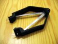
PLCC BIOS removal tool.
-
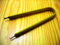
DIP BIOS removal tool.
-
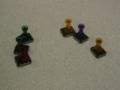
Push pins with cut off needles, attached to ROM chips with super glue.
-
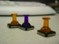
More push pins on ROM chips.


POST card
A POST card will save your life: it's the only output device (beside beeper) you have during the boot process. The term POST means Power On Self Test and comes from the original IBM specifications for the BIOS. Port 80 is a pre-defined port to which programs can output a byte. The POST card displays the byte in hex on its 2 digit display. We use a lot of POST codes in coreboot, so if you can tell us the POST code you see, we will have some idea of what happened.
If your coreboot machine is working properly, you will see it count up from 0xd0 to 0xd9 (while it is gunzipping the kernel) and then display 0x98 (Linux idle loop). There are POST cards with ISA bus, PCI bus, USB und parallel port connectors (the latter for laptops).
Often they carry status LEDs for ISA/PCI signals such as: IRDY, BIOS-access, FRAME, OSC, PCI-CLK, RESET, 12V, -12V, 5V, -5V, 3.3V. Some cards were known to not function because the mainboard switches off the CLK on their slot after non-standard registration on PCI.
-
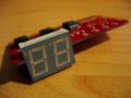
BIOS POST card for PCI.
-
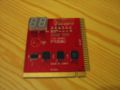
BIOS POST card for PCI and ISA.


PCI POST cards can be found in various places.
See also How can I write to port 0x80 from userspace.
- http://siliconkit.dnsalias.com/cart/index.tpcip.html
- http://www.elstonsystems.com/prod/pc_analyzer.html
- http://shopv2.elstonsystems.com/product_info.php/products_id/57
- http://www.uxd.com/trio.html
- http://www.soyousa.com/products/proddesc.php?id=261
Null-modem cable
A so-called null-modem cable is used for transmitting the output from a serial coreboot (or GRUB- or Linux-) console to another computer where a terminal program (such as minicom) can be used to display/save the messages.
-
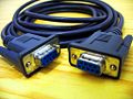
A null-modem cable.

Compact Flash IDE adaptor
solid state disk save time during the repeated boot process compared with regular hard disks.
- http://siliconkit.dnsalias.com/cart/index.tcfdp.html
- http://www.cwlinux.com/eng/products/products_ide2cf.php
- http://www.mini-box.com/s.nl/sc.8/category.14/.f
- http://www.acscontrol.com/Index_ACS.asp?Page=/Pages/Products/CompactFlash/IDE_To_CF_Adapter.htm
- http://www.pcengines.ch/cflash.htm
- http://www.psism.com/adcf.htm
- http://www.hsc-us.com/industrial/adapter/ATP.html (2xCF, one with hotswap!)
- http://www.mesanet.com/ (Choose DISK EMULATORS then CFADPTHD in the menu. 2xCF)
Oscilloscope
For hardware debugging purposes when it goes down the most atomic details. Consider logic analyzers as alternative.
In Circuit Emulator hardware debugger
allows very time-saving burn/debug cycles with added tracing capabilities but somewhat costly. Ownership makes you a true geek, however ;-)
coreboot SDK
In Circuit chip programmer
Should allow you to program your BIOS even if it is soldered to the motherboard.
EPROM emulators
These hardware devices pretend to be an EPROM chip.
- http://www.tech-tools.com/romtools.htm
- http://xtronics.com/memory/pktROM.htm
- http://www.tribalmicro.com/multirom/
- http://www.linuxselfhelp.com/HOWTO/Diskless-HOWTO-10.html (a larger list -- outdated)
USB debug devices
An alternative to a serial console may be a USB debug device. They are not so common yet. Their advantage is higher speed than a serial console. One might hook an FPGA to it for profiling purposes or some automated checks. Accessing a USB debug device from within BIOS is not different than other USB devices, and is part of the USB standard.
See also EHCI Debug Port.
How do I use a null-modem cable to get coreboot debugging output over a serial port?
- First, you'll want to set up a terminal program, e.g. minicom correctly.
$ minicom -s
 -> Serial port setup
 -> Press A and enter your COM device (ttyS0 or ttyS1 or ttyUSB0, depending on your COM port)
 -> Press E and choose "115200 8N1" (default)
 -> Disable Hardware and Software Flow Control (via F and G)
 -> Press enter to leave the menu
 -> Save setup as..
 ->   Enter "lb"
 -> Exit from minicom
- From now on, you can start minicom with the obove settings simply by typing:
$ minicom -o lb
What documentation do I need?
As much documentation as you can possibly get your hands on. At minimum, you will need the docs for the chipset.
There have been reports of people getting coreboot working by booting with the OEM BIOS. Then, they would read the static contents of the PCI config registers after boot. coreboot is then built to match the static contents read from the PCI config registers.
The problem with this approach is that chipsets generally require dynamic vs static configuration values during their initialization. The configuration register contents will change from one stage of initialization to the next. Since the contents of the registers read is only the final state of the configuration registers, the chipset won't be properly initialized if these are the only configuration values used.
Getting a mainboard up without chipset docs can be a very long and involved process.
What if my chipset docs are covered by an NDA?
If the documentation for your chipset covered by a NDA with no source release agreement, you won't be able to release your code back to the coreboot project in general, or you will violate the GPL. Many vendors accept releasing the source code, produced after reading such specs, while they don't allow the specs themselves to be revealed. Also, you can offer them the opportunity to review your code, before releasing it to the public.
Why is the code so complicated and what can I do to make it easier?
The reason is the complexity of the problem. We support a lot of hardware, and a given chip on a given board will most likely not be configured quite the same as the same chip on some other board. To help make code navigation easier, pick a target and build that target. Then, in the build directory, type make tags or make etags to get your favorite tags file.
How do I contribute my changes?
Please carefully read the Development Guidelines for more information.
How do I identify the BIOS chip on my mainboard?
Modern mainboards store the BIOS in a reprogrammable flash ROM chip. There are hundreds of different flash ROMs, with variables such as memory size, speed, communication bus (LPC vs. ISA/PCI) and packaging to name just a few. The three most common packages are called DIP, PLCC and TSOP. The BIOS copyright holders often place a fancy sticker on the BIOS chip showing a name or logotype, BIOS version, serial number and copyright notice.
DIP: Dual In-line Package
A rectangular black plastic block with lots of pins along the two longer sides of the package. DIP ROMs can be socketed which means they are detachable from the mainboard using physical force. Since they haven't been moved in and out of the socket very much (yet, hehe) they can appear to be quite difficult to release from the socket. One way to remove a DIP from a socket is by prying a thin screwdriver in between the plastic package and the socket, along the shorter sides where there are no pins, and then gently bending the screwdriver to push the DIP upwards, away from the mainboard. Alternate between the two sides to avoid bending the pins, and don't touch any of the pins with the screwdriver, see FAQ about ESD, electro-static discharge. If the DIP is soldered directly to the mainboard, it has to be desoldered in order to be reprogrammed outside the mainboard. If you do this, it's a good idea to solder a socket to the mainboard instead, to ease any future experiments.
PLCC: Plastic Leaded Chip Carrier
Black plastic block again, but this one is much more square. PLCC is becoming the standard for mainboards because of it's smaller physical size. PLCC can also be socketed or soldered directly to the mainboard. Socketed PLCC chips can be removed using a special PLCC removal tool, or using a piece of nylon line tied in a loop around the chip and pulled swiftly straight up, or bending/prying using small screwdrivers if one is careful. PLCC sockets are often fragile so the screwdriver approach is not recommended. While the nylon line method sounds onorthodox it works well. Desoldering PLCC can be painful without specialized desoldering equipment particularly because PLCC chips have leads on all four sides of the package.
TSOP: Thin Small-Outline Package
TSOP chip on a TSOP->DIP adapter
TSOPs are often used in embedded systems where size is important and there is no need for replacement in the field. It is possible to (de)solder TSOPs by hand, but it comes close to wizardry.
How do I (re-)flash the BIOS?
Out of mainboard BIOS (re)flash
If the BIOS chip is socketed, it can be removed and flashed in a rom/flash burner and quickly re-installed. Some of these burners cost $1000 and more plus they complete a flash in 1-2 minutes, but if you are willing to wait 5 minutes for a flash and manually set DIP switches, The Enhanced Willem Universal Programmer will do the job for only $40-60 USD. There are several models of the Willem Programmer, each supporting many chips, but not all, so be sure to get one that supports your BIOS chip. If your chip is PLCC, you will also need a PLCC chip extractor/puller or just thread nylon string under the PLCC chip from corner to corner and yank up it straight up.
Inside mainboard BIOS (re)flash
Download the appropriate flash update utility. Build the romimage as explained above and use the flash update utility to update the BIOS. Be warned that not all update utilities allow you to load your own BIOS image. For example, Intel decided to disallow it for the MS440GX mainboard (probably after hearing about us!) Here are some mainboard specific directions:
General
coreboot v2 contains a flash utility called flashrom in the util/flashrom directory. (Old versions had "util/flash_and_burn/flash_rom" instead).
Example:
bash$ sudo ./flashrom -V
Calibrating delay loop... Setting up microsecond timing loop
216M loops per second
ok
Found canidate at: 00000530-00000bc4
Found LinuxBIOS table at: 00000530
lb_table found at address 0xb7e1c530
LinuxBIOS header(24) checksum: 404a table(1684) checksum: 2766 entries: 14
vendor id: via part id: epia-m
Enabling flash write on VT8235...OK
Trying Am29F040B, 512 KB
probe_29f040b: id1 0x20, id2 0xe2
Trying ST29F040B, 512 KB
probe_29f040b: id1 0x20, id2 0xe2
ST29F040B found at physical address: 0xfff80000
Flash part is ST29F040B
OK, only ENABLING flash write, but NOT FLASHING.
If neither utility supports your chip, then you could either use the DOS uniflash utility, or use its source code, which is also available for download from the uniflash site (in Turbo Pascal 7) as a reference for adding support for your flash chip to "flash_rom". Uniflash supports a lot of different flash chips, and chip interfaces. It has untested support for PCI expansion card flash BIOS, such as on RTL8139 Ethernet card (32pin DIL), which allows flashing on the NIC if manufacturer provides the circuitry.
Another tool which runs in linux is flasher.
SiS 630/950 M/Bs
Ollie Lho provided us with flash utilities for these boards under freebios/util/sis. flash_on turns on the flash write enable. This needs to be run before loading the DoC drivers. flash_rom allows you to use your SiS 630/950 M/Bs as a flash programmer. It currently supports JEDEC flash parts, AMD am29f040b models, MXIC MX29F002 models, and SST28SF040C models.
Intel L440GX
Get the System Update Package directly from Intel. mcopy the ten files created from running make phlash onto the Intel flash burner disk and use the update utility to burn the BIOS. To restore the original BIOS, set the recovery boot jumper on the motherboard, put the floppy in, and it will load and reflash the original BIOS. How do I actually burn a flash ROM?
Buy your favorite flash burner (we use a Needham Electronics EMP 30). Use make floppy to create the romimage and copy it to a floppy. Then use the provided software to burn the flash.
BIOS Savior RD1
There are some posts about the BIOS Savior RD1 that suggest its integrated flash device is of low quality; it may take 10 or more flash programming attempts to get a good update to the RD1 flash device. As a result, the following steps have proven to be successful while using the RD1:
- Step 1 - While the system is powered down, remove the original BIOS device from the mainboard and insert it into the RD1's socket.
- Step 2 - Insert the RD1 into the mainboard's flash BIOS socket.
- Step 3 - Boot the system with the RD1 set to boot from the original flash device from the mainboard.
- Step 4 - Program the original BIOS image (or other known good BIOS image) into the RD1's integrated flash device. Do this as many times as needed until the device is properly programmed and the system boots corectly from the RD1's integrated flash device. Be sure to check the settings on the RD1 so that the proper flash device is now being programmed. If the RD1 is not set correctly the working BIOS image will be erased and the system will not boot!
- Step 5 - Program the test BIOS image (usually coreboot images are among this group) into the original flash device from the mainboard. The original BIOS device usually programs OK on the first attempt. Be sure to check the settings again on the RD1 so that the proper flash device is being programmed!
The RD1 has been used in the above fashion with great success on the Tyan S2885 mainboard. Unfortunately the RD1 does not work on the nVidia CK8-04 CRB mainboard. The CK8-04 CRB may require a flash device that the RD1 does not support.
The RD1 has worked well as a "do nothing" adapter that allows swapping the BIOS flash device between a flash burner and a mainboard without any wear to the mainboard's BIOS socket.
Can I do any serious damage mucking around with this stuff?
Any time you stick your hand into an open machine while the power is on, you're risking life and limb. That said, there are also some other not-so-nice things that can happen if you mess up (not that we would know).
- Incorrect insertion of the flash (1 casualty)
- Incorrect jumper settings (1 casualty)
- Aggressive and/or inappropriate use of metal objects such as screwdrivers (2 casualties)
- Miscellaneous miswirings and mishandlings (3+ casualties)
remember: make sure your important data is on a disconnected drive while you experiment.
A note on electrostatic discharge (ESD) and ESD protection (thanks to Bari Ari)
ESD can damage disk drives, boards, DoC's and other parts. The majority of the time, ESD events cause the component to degrade, but not fail testing procedures, resulting in failure at a later date. Because components do not fail immediately, technicians often underestimate the cost of not using ESD prevention measures. Provide at minimum some ESD protection by wearing an antistatic wrist strap attached to the chassis ground on your system when handling parts.
Always handle boards carefully. They can be extremely sensitive to ESD. Hold boards only by their edges. After removing a board from its protective wrapper or from the system, place it component side up on a grounded, static free surface. Use a conductive foam pad if available. Do not slide the board over any surface.
To further reduce the chances of ESD, you should create an ESD safe workstation that includes at minimum:
- Conductive rubber mat, with a lead wire that can be connected to a metal surface to create a ground.
- ESD wrist strap, which has a resistor inside the strap and a lead wire that can be connected to a metal surface as a ground. The grounding wire on the wrist strap should have between 1 and 10 Megaohms of resistance. The resistor should protect you in case you come in contact with a voltage source. If the resistor is bad or not included, the wrist strap is useless. An accidental shock could be serious and even deadly!
- Table or workspace that is clean, clear of dust, and away from electrical machinery or other equipment that generates electrical currents.
The idea is to ensure that all components you are going to interact with have the same charge. By connecting everything to the computer case, you ensure that the components of the case, the chair, and your body all have the same charge. If every object has the same charge, the electrons will not jump from one object to another minimizing the risk of ESD damage.
What is a PIRQ table?
There's a good description of the BIOS implementation of the PIRQ in the red PCI book, and here's a description of the $PIR data structure.
coreboot saves the $PIR data structure between 0xf0000 & 0x100000. Search for $PIR and then save it before copying over the BIOS.
See also the ADLO README for more information.
How do I set up etherboot with coreboot?
Note from Ron: I have edited this somewhat to remove Geode-specific items.
Christer Weinigel writes:
To: rminnich@lanl.gov
Cc: linuxbios@lanl.gov
Subject: Re: LinuxBIOS + Etherboot HOWTO?

I had some trouble using LinuxBIOS + etherboot...

My bad, I messed up and used mkelfImage-1.6 that I got from ftp.lnxi.com, when I realized that I ought to use the one from freebios/util everything started working.

Here's what I did to get LinuxBIOS + Etherboot loading and booting a Linux kernel using TFTP.

  /Christer

Get etherboot-5.0 from the CVS tree on etherboot.sourceforge.net.

Modify etherboot-5.0/src/Config, comment out:

   # BIOS select don't change unless you know what you are doing
   #CFLAGS32+=     -DPCBIOS

and uncomment the following:

   # Options to make a version of Etherboot that will work under linuxBIOS.
   CFLAGS32+= -DLINUXBIOS -DCONFIG_TSC_CURRTICKS  -DCONSOLE_SERIAL \
              -DCOMCONSOLE=0x3f8 -DCOMPRESERVE -DCONFIG_PCI_DIRECT -DELF_IMAGE

Compile Etherboot to make an elf file for your ethernet card:

    make bin32/natsemi.elf

Compile and install mkelfImage from freebios/util/mkelfImage.

Create a bootimage to put on your TFTP server:

   mkelfImage --command-line="root=/dev/hda2 console=ttyS0,38400" \
              --kernel vmlinux -o /tftpboot/kernel

Finally, make sure that your BOOT/DCHP server is answering and that the TFTP server is active.

Tell LinuxBIOS to boot an elf Image, and tell LinuxBIOS where it is:

   option USE_ELF_BOOT=1

I have placed natsemi.elf in the first 64k of my BIOS flash chip, and LinuxBIOS in the second 64k.

   insmod bios.o
   dd if=natsemi.elf of=/dev/bios bs=64k
   dd if=linuxbios.rom of=/dev/bios bs=64k seek=1

Finally boot LinuxBIOS.
How do I set GEODE graphics and video?
There is no Geode graphics support in coreboot. Install the Geode framebuffer driver for console graphics and the X driver for X support on your Geode Linux image. Current kernel and X distributions contain the required drivers. Until the driver loads there is only serial console output.
Driver source:
2.6.23 kernel framebuffer driver
How do I set up testbios?
Please read the testbios FAQ.
/usr/sbin/iasl: Command not found
If you see this error, you have to install iasl, Intel's ASL Optimizing Compiler:
- SUSE ships it in the pmtools package (pmtools-20050823-3.x86_64.rpm, pmtools-20050823-3.i586.rpm). If you want to run rpmbuild --rebuild: pmtools-20050823-3.src.rpm.
- Debian ships it in the iasl package (apt-get install iasl).
- You can also download the latest version of the source code.
How can I write to POSTcard port 0x80 from userspace?
This might be useful in some situations, and to output a number to a POST card:
printf "\001" | dd bs=1 seek=128 of=/dev/port
In DOS (not Windows XP) use:
mov al, 42; out al, 80h
To output 42 type
o 80 42
in DOS debug.exe.
Is coreboot applying x86 microcode patches?
And if yes, can they be modified?
Answer: this field is little documented. Few people think, however, that system design can seriously be improved by modifications here ( µCode patches mostly disable erraneous functions and opcodes).
How can I retrieve a good video bios?
Note: if you are following these instructions to build coreboot for your motherboard, this is only necessary if you have a motherboard with an embedded VGA card. If your VGA is an add-on card, coreboot will find and run the ROM by itself.
Anton Borisov has released a number of tools under the GPL (v2) to extract the VGA BIOS from the BIOS ROM images provided by the supplier of your motherboard.
You can download them here:
 Award BIOS: http://kaos.ru/biosgfx/download/awardeco-0.2.src.tar.gz
 AMI BIOS: http://www.kaos.ru/biosgfx/download/AmiDeco_0.31e.src.tar.gz
 Insyde BIOS: http://www.kaos.ru/biosgfx/download/InsyDeco_0.3.src.tar.gz
 Phoenix BIOS: http://www.kaos.ru/biosgfx/download/PhoenixDeco_0.33.src.tar.gz
See the Tyan S2881 Build Tutorial for more information on how to use these tools.
Can I put coreboot into a PCI expansion ROM?
There's little use in doing that, as a lots of initialization has already been done by the proprietary BIOS (or coreboot) by the time the PCI expansion ROM is executed. It won't be possible to run coreboot from a PCI expansion ROM after a proprietary BIOS has already been running for instance.
Note: The Intel ICH7 southbridge seems to allows booting from PCI ROMs (not arbitrary PCI expansion ROMs as used on graphics cards, SCSI controllers, etc.) -- maybe this should be investigated in order to check if or how it might be useful.
Obsolete FAQ items
Please see FAQ/Obsolete for (probably) obsolete FAQ items.