File list
Jump to navigation
Jump to search
This special page shows all uploaded files.
| Date | Name | Thumbnail | Size | User | Description | Versions |
|---|---|---|---|---|---|---|
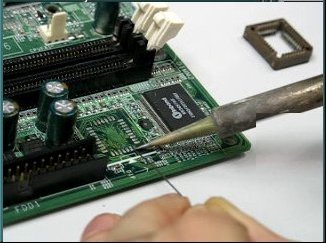
| 16:26, 26 March 2009 | Pads after desoldering.jpg (file) |  |
177 KB | Uwe | Pads after desoldering the ROM chip. Author: Uwe Hermann {{PD-self}} | 1 |
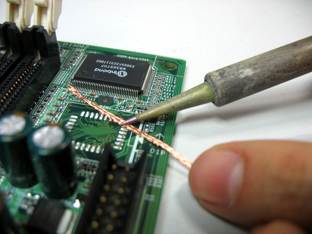
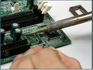
| 16:28, 26 March 2009 | Pads cleaning.jpg (file) |  |
146 KB | Uwe | Cleaning the pads with desoldering wick. Author: Uwe Hermann {{PD-self}} | 1 |
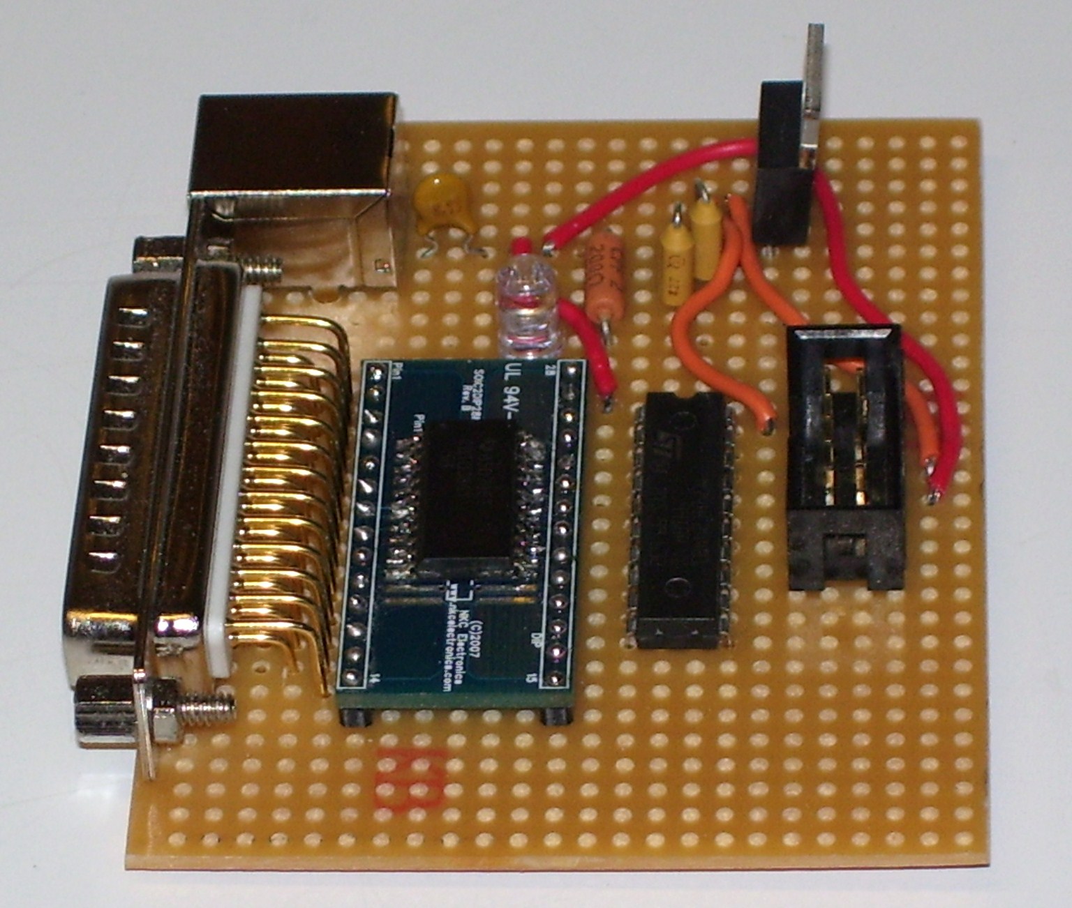
| 13:01, 12 February 2009 | Paraflasher.jpg (file) |  |
442 KB | Linux junkie | This is my first build of the paraflasher. | 1 |
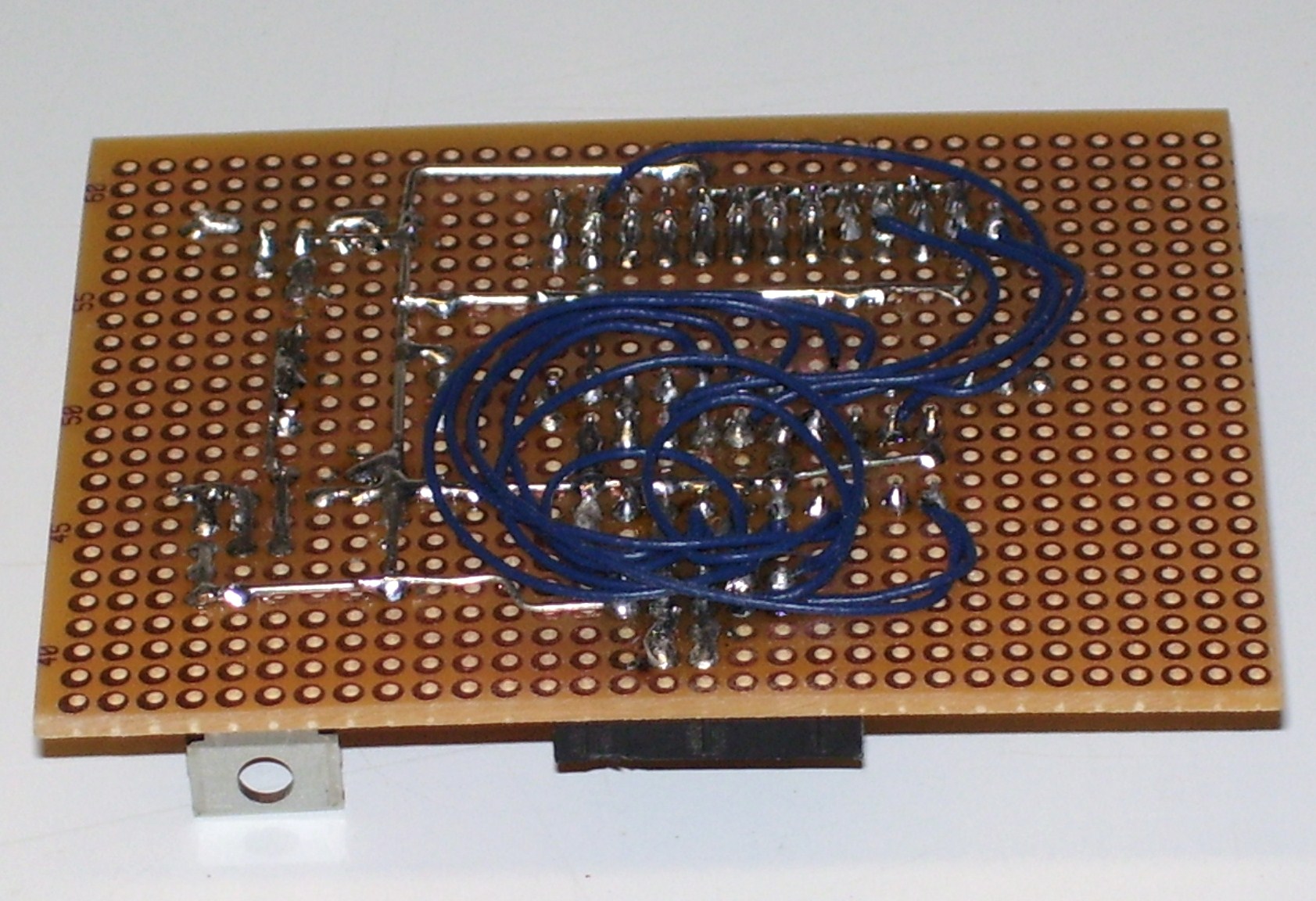
| 13:05, 12 February 2009 | Paraflasher bottom.jpg (file) |  |
412 KB | Linux junkie | Ugly bottom picture of the paraflasher | 1 |
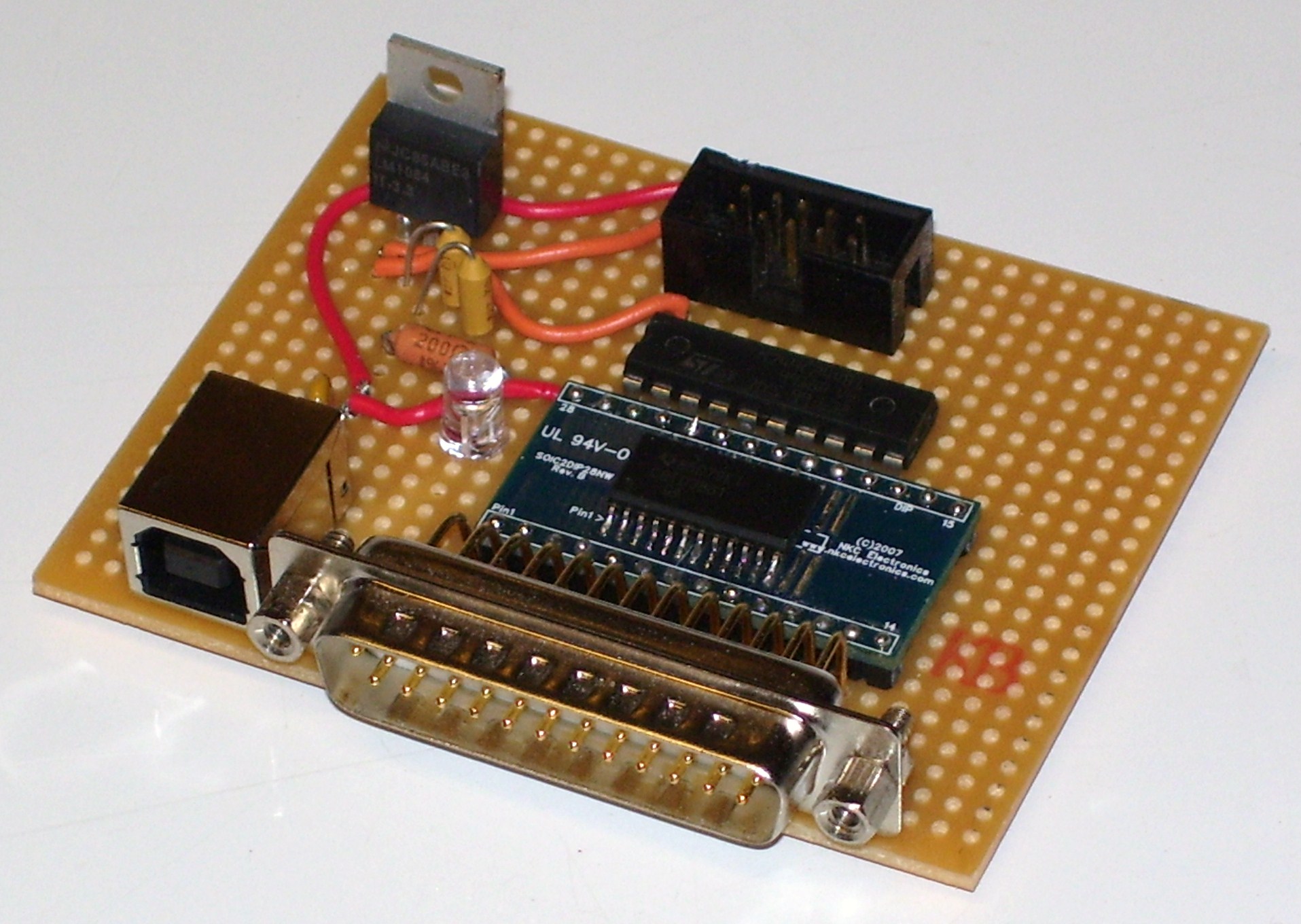
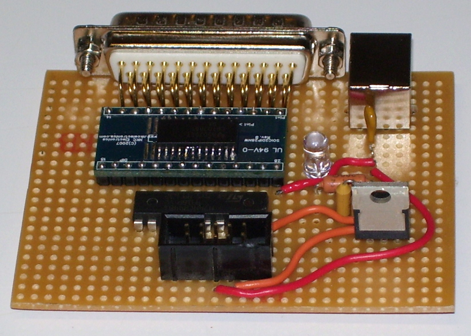
| 13:12, 12 February 2009 | Paraflasher front.jpg (file) |  |
369 KB | Linux junkie | Front picture of the paraflasher | 1 |
| 13:09, 12 February 2009 | Paraflasher left.jpg (file) |  |
376 KB | Linux junkie | Left picture of the paraflasher | 1 |
| 13:08, 12 February 2009 | Paraflasher right.jpg (file) |  |
376 KB | Linux junkie | Right picture of the paraflasher | 1 |
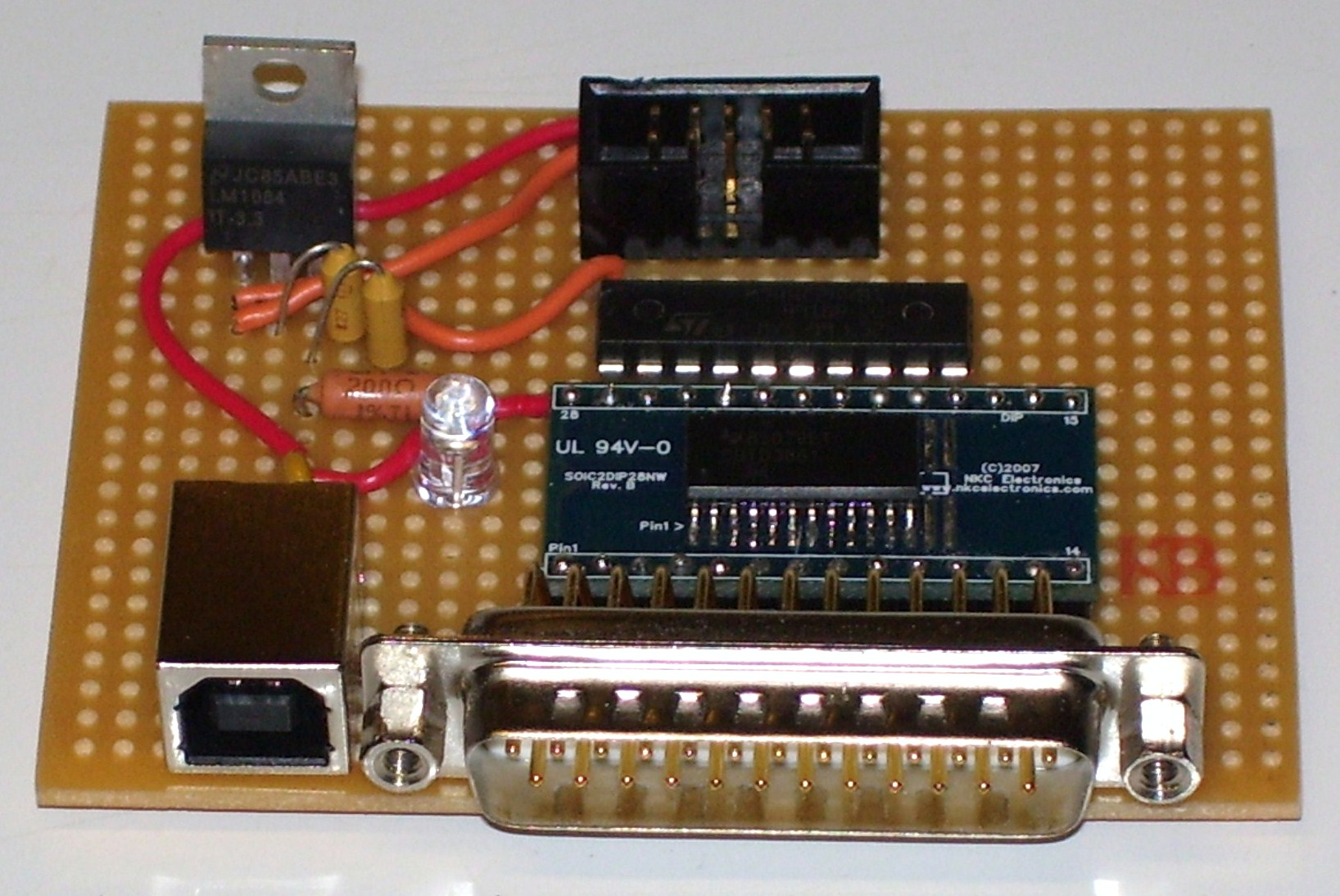
| 13:04, 12 February 2009 | Paraflasher top.jpg (file) |  |
388 KB | Linux junkie | Top picture of the paraflasher | 1 |
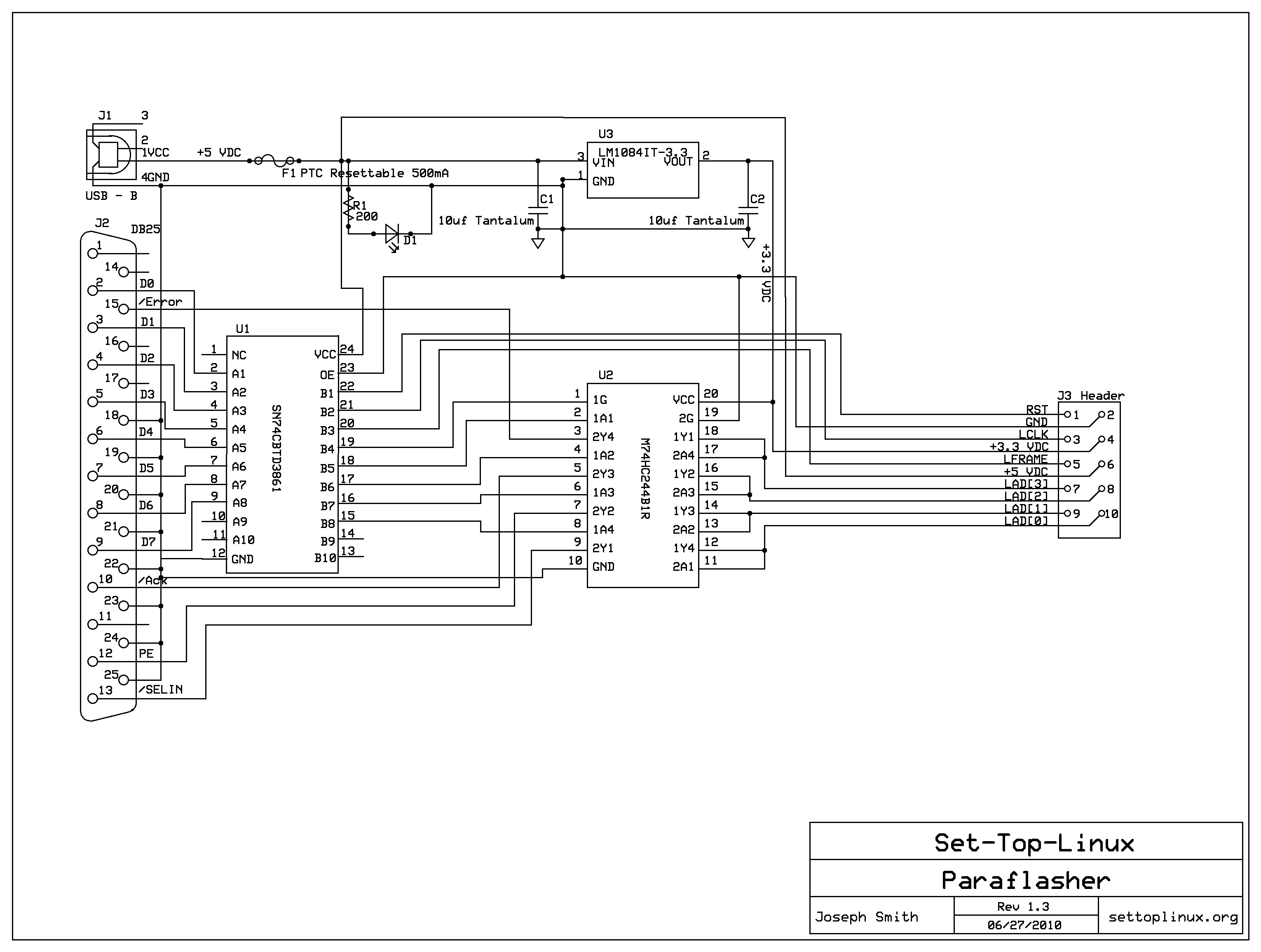
| 03:03, 28 June 2010 | Paraflashersch.jpg (file) |  |
521 KB | Linux junkie | New design | 2 |
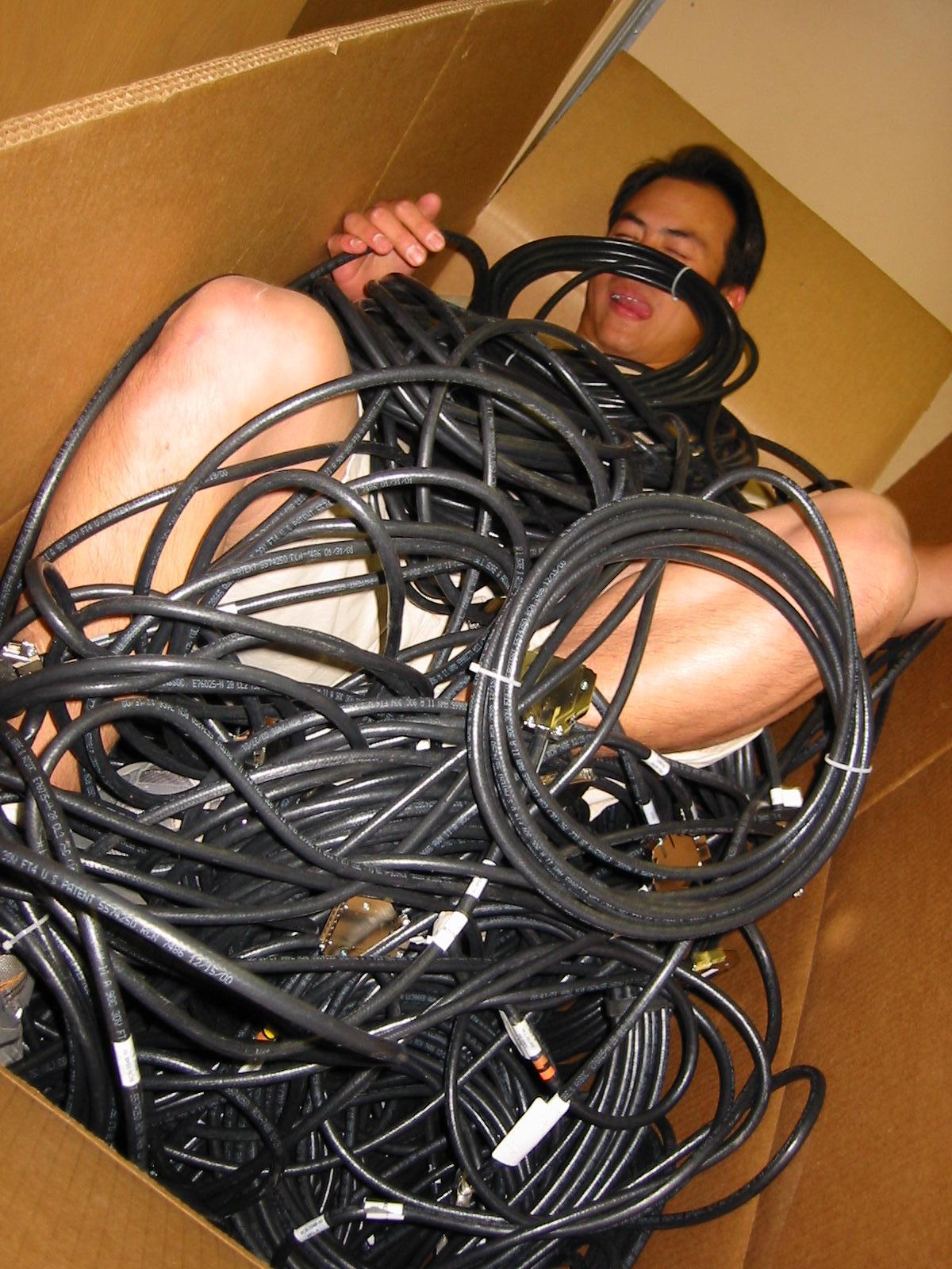
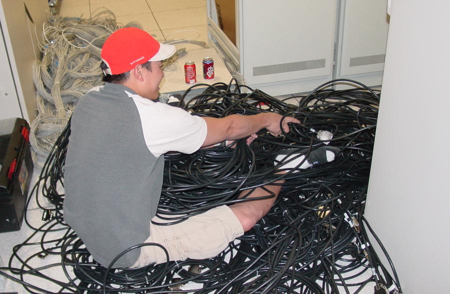
| 20:55, 13 October 2006 | Paul pulling.jpg (file) |  |
50 KB | Uwe | Author: Unknown License: Unknown Category:Ed | 1 |
| 15:23, 17 June 2012 | Pci1002,9802.rom.gz (file) | 39 KB | Alien | VGA ROM for the graphics adapter embedded on AMD E350 | 1 | |
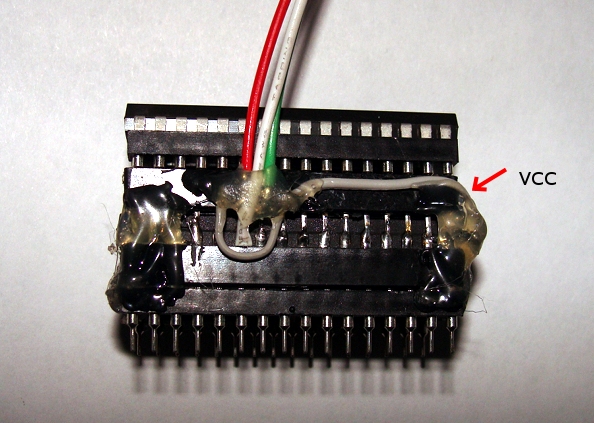
| 21:48, 18 May 2011 | Pie1.jpg (file) |  |
201 KB | Mrtadis | VCC is connected to pull-up resistors | 1 |
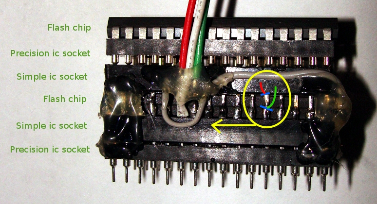
| 21:50, 18 May 2011 | Pie2.jpg (file) |  |
305 KB | Mrtadis | Detailed "pie" structure. In a yellow ellipse you can see blue lines, that shows how to bend pins. | 1 |
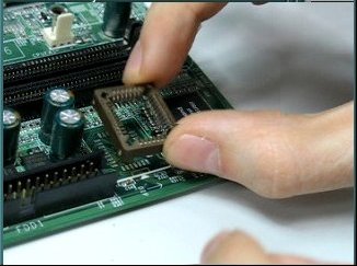
| 02:49, 27 March 2009 | Place plcc socket.jpg (file) |  |
20 KB | Uwe | Place the socket on the pads. Author: Uwe Hermann {{PD-self}} | 1 |
| 20:29, 6 October 2015 | Plate.jpg (file) |  |
66 KB | Phcoder | 1 | |
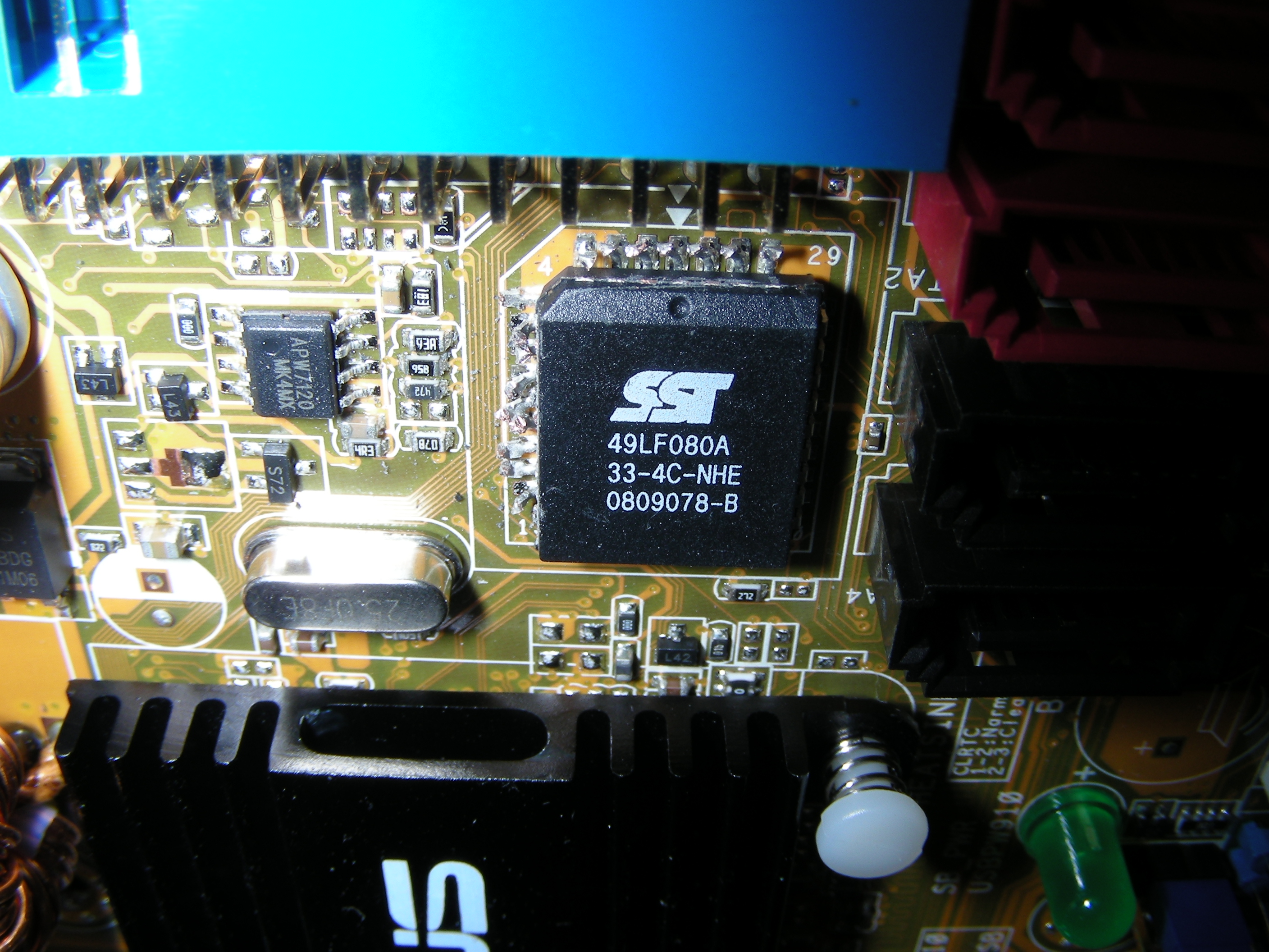
| 20:29, 6 October 2015 | Plate2.jpg (file) |  |
33 KB | Phcoder | 1 | |
| 12:51, 31 March 2009 | Plcc-legs-cut-off-on-two-sides.jpg (file) |  |
1.94 MB | Ward | 1 | |
| 13:11, 31 March 2009 | Plcc-no-legs.jpg (file) |  |
282 KB | Ward | PLCC chip with the legs cut off. Note how I cut as close to the chip packaging as possible. Author: Ward Vandewege {{PD-self}} | 1 |
| 12:56, 31 March 2009 | Plcc-only-legs-remain.jpg (file) |  |
1.85 MB | Ward | The PLCC chip was removed from the motherboard, only the legs remain. Author: Ward Vandewege {{PD-self}} | 1 |
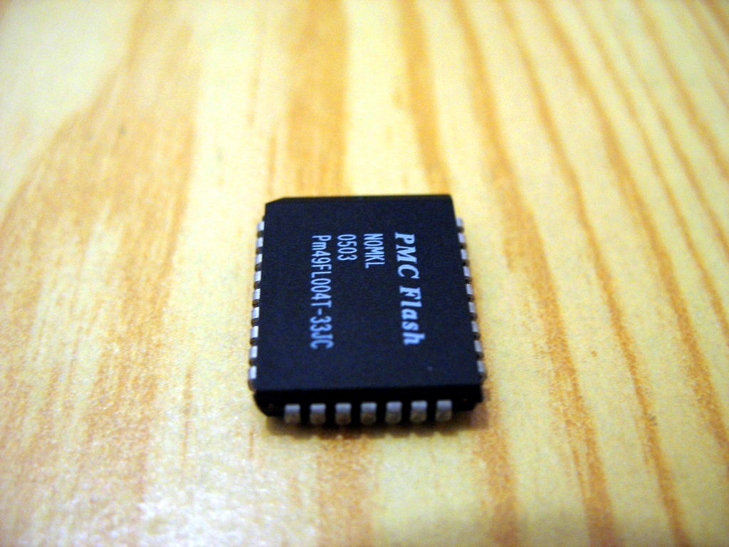
| 22:11, 27 March 2009 | Plcc32 chip.jpg (file) |  |
142 KB | Uwe | PLCC32 chip. Author: Uwe Hermann {{PD-self}} | 1 |
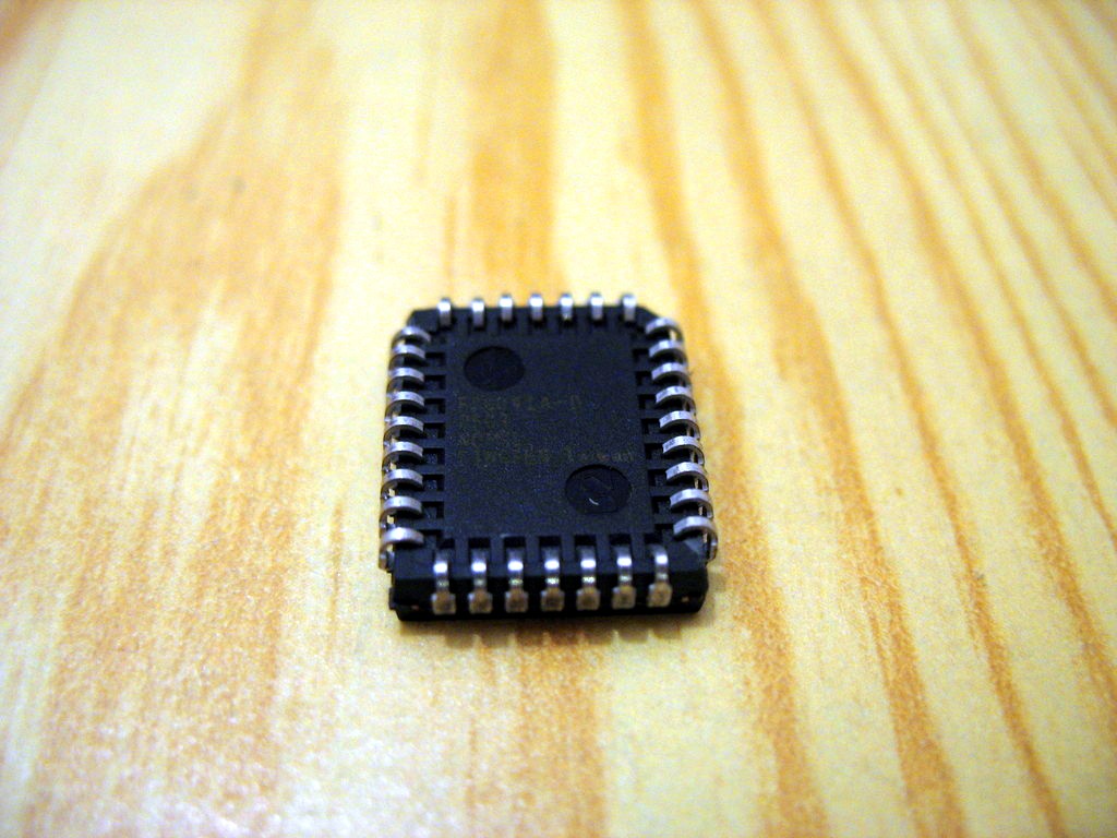
| 22:11, 27 March 2009 | Plcc32 chip back.jpg (file) |  |
150 KB | Uwe | PLCC32 chip. Author: Uwe Hermann {{PD-self}} | 1 |
| 13:53, 14 June 2009 | Plcc32 in socket.jpg (file) |  |
215 KB | Uwe | PLCC32 chip in a socket. Author: Uwe Hermann {{PD-self}} | 1 |
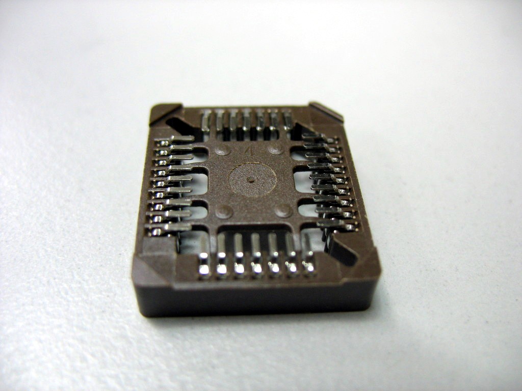
| 16:14, 26 March 2009 | Plcc socket.jpg (file) |  |
110 KB | Uwe | A PLCC socket (SMD type). Author: Uwe Hermann {{PD-self}} | 1 |
| 17:08, 26 March 2009 | Plcc socket back side.jpg (file) |  |
111 KB | Uwe | PLCC socket, back side. Author: Uwe Hermann {{PD-self}} | 1 |
| 17:09, 26 March 2009 | Plcc socket back side without plastic.jpg (file) |  |
108 KB | Uwe | PLCC socket, back side, without middle plastic. Author: Uwe Hermann {{PD-self}} | 1 |
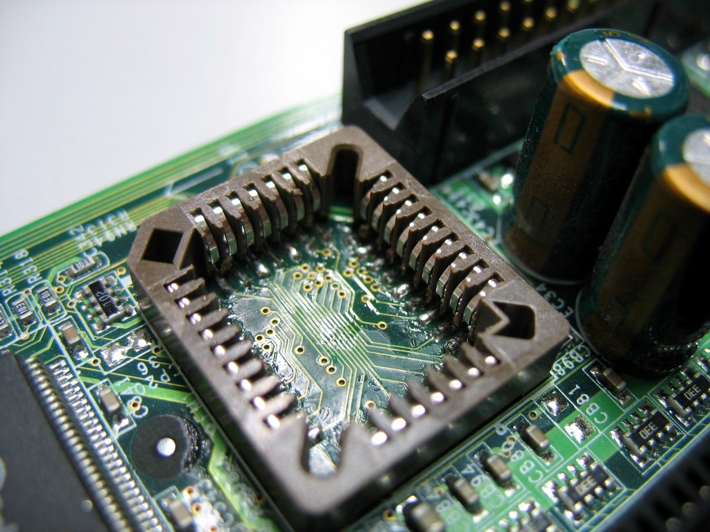
| 16:15, 26 March 2009 | Plcc socket soldered.jpg (file) |  |
198 KB | Uwe | Done. PLCC socket successfull soldered onto the board. Author: Uwe Hermann {{PD-self}} | 1 |
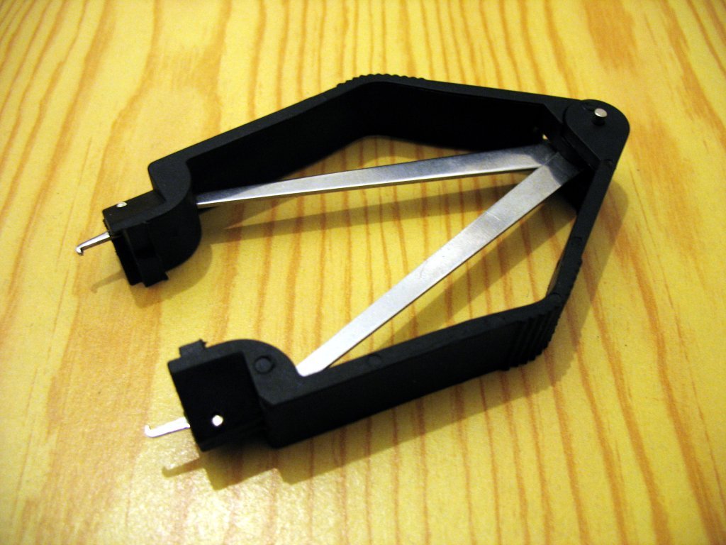
| 12:25, 30 March 2007 | Plcc tool.jpg (file) |  |
119 KB | Uwe | A PLCC BIOS chip removal tool. Author: Uwe Hermann License: Public Domain | 1 |
| 16:16, 26 March 2009 | Pliers1.jpg (file) |  |
120 KB | Uwe | Pliers and a PLCC socket. Author: Uwe Hermann {{PD-self}} | 1 |
| 16:16, 26 March 2009 | Pliers2.jpg (file) |  |
130 KB | Uwe | Pliers and a modified PLCC socket (removed middle part for easier soldering). Author: Uwe Hermann {{PD-self}} | 1 |
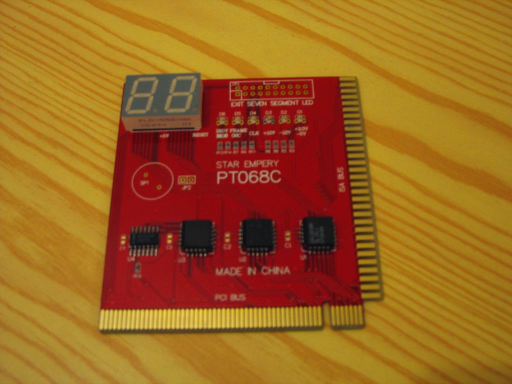
| 23:20, 26 April 2007 | Post card1.jpg (file) |  |
89 KB | Uwe | A BIOS POST card for PCI. Author: Uwe Hermann License: Public Domain | 1 |
| 23:20, 26 April 2007 | Post card2.jpg (file) |  |
92 KB | Uwe | A BIOS POST card for PCI and ISA. Author: Uwe Hermann License: Public Domain | 1 |
| 02:49, 27 March 2009 | Prepare two pads.jpg (file) |  |
22 KB | Uwe | Prepare a pad in one corner of the socket. Author: Uwe Hermann {{PD-self}} | 1 |
| 02:50, 27 March 2009 | Prepare two pads2.jpg (file) |  |
23 KB | Uwe | Prepare a pad in the opposite corner of the socket. Author: Uwe Hermann {{PD-self}} | 1 |
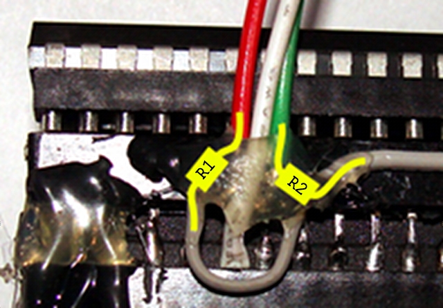
| 21:52, 18 May 2011 | Pull-ups.jpg (file) |  |
156 KB | Mrtadis | Pull-ups are connected like that. Please note that green and red wires are also connected to their corresponding flash chip's chip select signal. | 1 |
| 20:59, 13 October 2006 | Pump naps.jpg (file) |  |
275 KB | Uwe | Author: Unknown License: Unknown Category:Ed | 1 |
| 20:55, 13 October 2006 | Pump pulling.jpg (file) |  |
84 KB | Uwe | Author: Unknown License: Unknown Category:Ed | 1 |
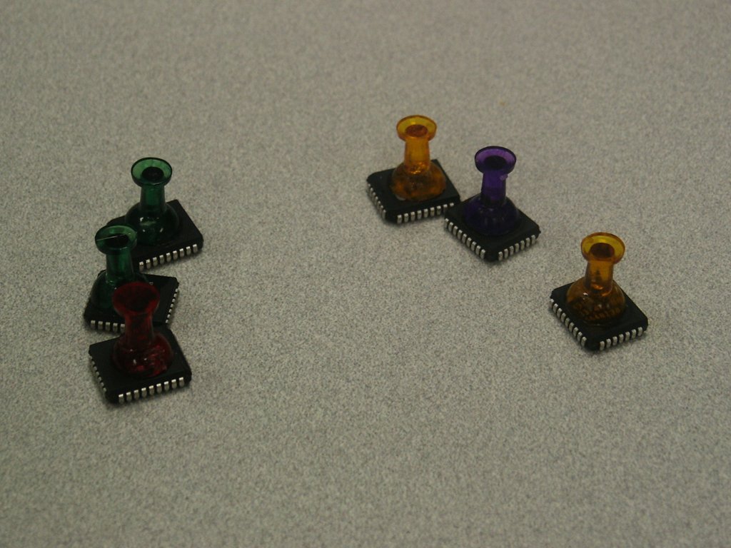
| 00:55, 11 April 2007 | Pushpin roms 1.jpg (file) |  |
133 KB | Uwe | Push pins with cut off needles, attached to ROM chips with super glue. Author: Randall Philipson <rtphilipson@cox.net> License: [http://www.linuxbios.org/pipermail/linuxbios/2007-April/019815.html Public Domain] | 1 |
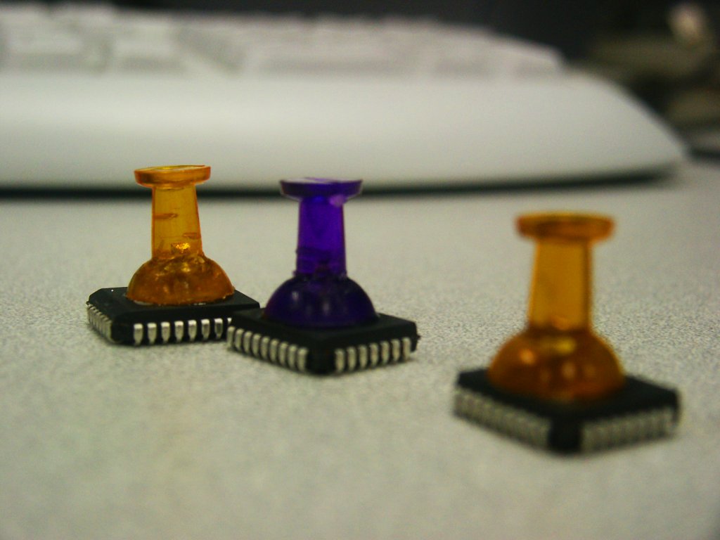
| 00:55, 11 April 2007 | Pushpin roms 2.jpg (file) |  |
76 KB | Uwe | Push pins with cut off needles, attached to ROM chips with super glue. Author: Randall Philipson <rtphilipson@cox.net> License: [http://www.linuxbios.org/pipermail/linuxbios/2007-April/019815.html Public Domain] | 1 |
| 10:03, 10 December 2012 | Qemu coreboot coreinfo.zip (file) | 256 KB | XVilka | Using coreboot latest commit 1224626e3b6eef255b9faac60a18807acebc1f3d | 3 | |
| 11:58, 1 May 2008 | Qemu coreboot filo.zip (file) | 65 KB | Uwe | QEMU BIOS image containing coreboot v3 (r672) and FILO (r45). | 1 | |
| 23:33, 31 March 2008 | Qemu coreboot invaders.zip (file) | 26 KB | Uwe | QEMU BIOS image containing coreboot v3 (r647) and the invaders payload. | 1 | |
| 00:22, 18 April 2008 | Qemu coreboot memtest.zip (file) | 58 KB | Uwe | QEMU BIOS image containing coreboot v3 (r656) and Memtest86 (3.4) with serial support enabled. | 1 | |
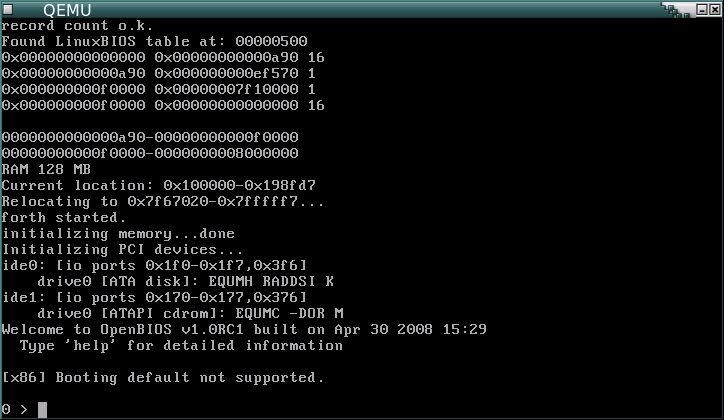
| 13:37, 30 April 2008 | Qemu coreboot openbios.png (file) |  |
12 KB | Uwe | coreboot v3 (r672) + OpenBIOS (r186) as payload in QEMU. Author: Uwe Hermann {{PD-self}} | 1 |
| 13:39, 30 April 2008 | Qemu coreboot openbios.zip (file) | 79 KB | Uwe | QEMU BIOS image containing coreboot v3 (r672) and OpenBIOS (r186). | 1 | |
| 18:32, 6 November 2009 | Qemu coreboot seabios.zip (file) | 66 KB | Uwe | QEMU BIOS image containing coreboot v2 (rTODO) and SeaBIOS (rTODO). | 1 | |
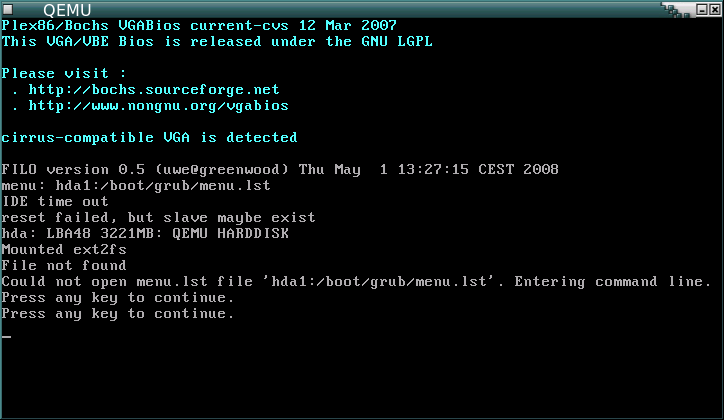
| 12:00, 1 May 2008 | Qemu filo.png (file) |  |
12 KB | Uwe | coreboot v3 (r672) + FILO (r45) as payload in QEMU. Author: Uwe Hermann {{PD-self}} | 1 |
| 12:01, 1 May 2008 | Qemu filo prompt.png (file) |  |
7 KB | Uwe | coreboot v3 (r672) + the FILO (r45) prompt in QEMU. Author: Uwe Hermann {{PD-self}} | 1 |
| 00:17, 9 April 2008 | Qemu libpayload tint.zip (file) | 35 KB | Uwe | QEMU BIOS image containing coreboot v3 (r656), libpayload (r3225), and tint 0.03b patched to be built against libpayload. | 1 | |
| 00:11, 18 April 2008 | Qemu memtest.png (file) |  |
10 KB | Uwe | coreboot v3 (r656) + Memtest86 payload in QEMU. Author: Uwe Hermann {{PD-self}} | 1 |
| 18:51, 6 November 2009 | Qemu seabios.png (file) |  |
11 KB | Uwe | coreboot v2 (r4917) + SeaBIOS (9eebe66a9978165cfa91f2266c97fa5d0aa6ef2e, 2009-11-04) as payload in QEMU. Author: Uwe Hermann {{PD-self}} | 1 |